
Mechanical arm joint module with two degrees of freedom

A technology of joint modules and mechanical arms, applied in the directions of manipulators, manufacturing tools, joints, etc., can solve the problems of non-concentricity, difficult control, complicated connection, etc., and achieve the effect of easy processing, convenient disassembly and installation, and low cost.

Inactive Publication Date: 2010-03-03
陈宁
View PDF0 Cites 12 Cited by
  • Summary
  • Abstract
  • Description
  • Claims
  • Application Information

AI Technical Summary

Problems solved by technology

[0003] The purpose of the present invention is to solve the problems that the existing mechanical arm joints are composed of a single axis, and several degrees of freedom are not concentric, the control is difficult and the connection is complicated, and a two-degree-of-freedom mechanical arm joint module is provided.

Method used


Image

  • Mechanical arm joint module with two degrees of freedom

Examples


specific Embodiment approach 1

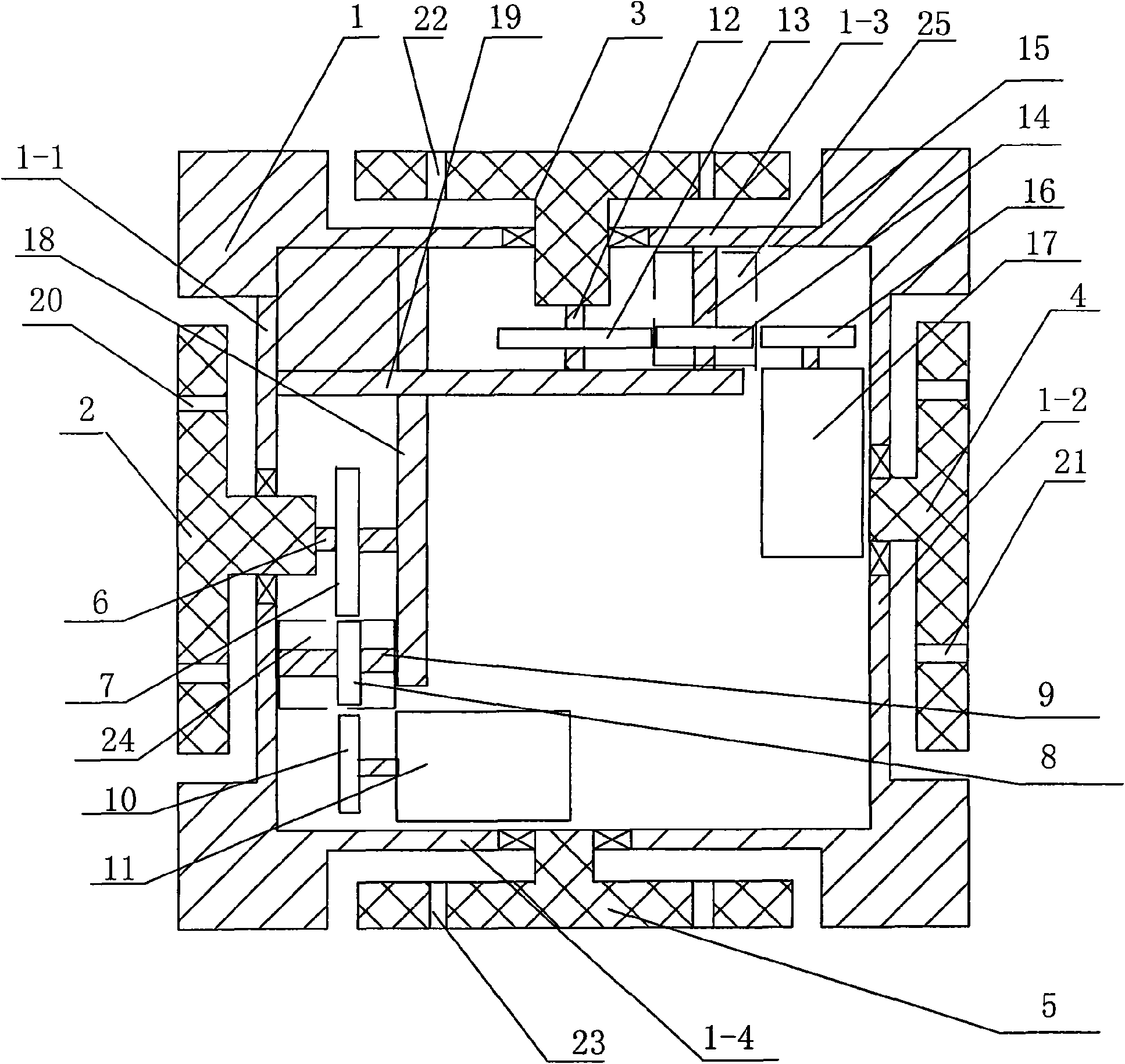
[0007] Specific implementation mode one: combine figure 1 Describe this embodiment, the manipulator joint module of this embodiment consists of a cubic box 1, a first output turntable 2, a second output turntable 3, a first follow-up turntable 4, a second follow-up turntable 5, and a first output turntable 6 , the first gear 7, the first reduction mechanism 24, the second gear 10, the first motor 11, the second output shaft 12, the third gear 13, the second reduction mechanism 25, the fourth gear 16, the second motor 17, the second A fixed frame 18 and a second fixed frame 19 are formed, and the left side wall, right side wall, upper end surface, and lower end surface of the cubic box 1 are respectively defined as the first side wall 1-1 and the second side wall 1-2. , the first end face 1-3 and the second end face 1-4, the first fixed frame 18 and the second fixed frame 19 are arranged in the described cubic box body 1, and the first fixed frame 18 and the first side wall 1- ...

specific Embodiment approach 2

[0008] Specific implementation mode two: combination figure 1 Describe this embodiment, the first reduction mechanism 24 of this embodiment is composed of a first differential gear set 8 and a plurality of first differential gear shafts 9, the gears in the first differential gear set 8 are sleeved on On the corresponding first differential gear shaft 9, the number of gears and the transmission ratio of the first differential gear set 8 are selected according to the single-axis torque and speed parameters of the mechanical arm, and this connection structure corresponds to the parameters of the mechanical arm , The overall disassembly and assembly are convenient and easy to maintain. Other components and connections are the same as those in the first embodiment.

specific Embodiment approach 3

[0009] Specific implementation mode three: combination figure 1 Describe this embodiment, the second reduction mechanism 25 of this embodiment is composed of the second differential gear set 14 and a plurality of second differential gear shafts 15, the gears in the second differential gear set 14 are sleeved on On the corresponding second differential gear shaft 15, the number of gears and the transmission ratio of the second differential gear set 14 are selected according to the single-axis torque and speed parameters of the mechanical arm, and this connection structure corresponds to the parameters of the mechanical arm , The overall disassembly and assembly are convenient and easy to maintain. Other components and connections are the same as those in the first embodiment.

[0010] Working principle: Fix the mechanical arm to the cubic box 1 through the first through hole 20, the second through hole 21, the third through hole 22 and the fourth through hole 23, respectively,...


PUM


Abstract

The invention relates to a mechanical arm joint module with two degrees of freedom. The mechanical arm joint module aims at solving the problems that the existing mechanical arm joint is formed by uniaxial combination, and has a plurality of non-concentric degrees of freedom, great control difficulty, and complex connection. A first output rotating disc and a first output rotating shaft are connected by transmission, the first output rotating shaft is fixed on a first fixed frame, a first following-up rotating disc is arranged on a second side wall, a first gear and the first output rotating shaft are fixedly connected, the first gear is meshed with an input end of a first speed-reducing mechanism, an output end of the first speed-reducing mechanism is meshed with a second gear, the firstspeed-reducing mechanism is fixedly arranged on the first fixed support, the second gear is arranged on an output shaft of a first motor, a transmission structure of a second output rotating disc is the same with that of the first output rotating disc, and the second output rotating disc and the first output rotating disc are vertically arranged. The mechanical arm joint module is used for controlling a mechanical arm to complete the special actions.

Description

technical field [0001] The invention relates to a mechanical arm joint module. Background technique [0002] The design of the multifunctional manipulator focuses on the design of the joints of the manipulator. At present, robot joints in Europe, America, including Japan are mostly composed of single-axis combinations. In the production of manipulator joints, the concentricity of the degrees of freedom is a difficult link to guarantee. To strictly ensure the concentricity, it needs the support of a more complex and precise mechanical structure. Once the two degrees of freedom are not concentric, it will affect the system. Stability and structural strength put forward higher requirements, and also increase the difficulty of control. Contents of the invention [0003] The purpose of the present invention is to provide a two-degree-of-freedom manipulator joint module in order to solve the problems that the existing manipulator joints are composed of a single axis, the degre...

Claims


Application Information

Patent Timeline
IPC IPC(8): B25J17/00
Inventor 刘志锋李官茂陈晓光陈宁王涛
Owner 陈宁
Features
  • Generate Ideas
  • Intellectual Property
  • Life Sciences
  • Materials
  • Tech Scout
  • Unparalleled Data Quality
  • Higher Quality Content
  • 60% Fewer Hallucinations
Learn More