Automobile air window

A technology for ventilation windows and automobiles, which is applied to vehicle components, superstructures, roofs, etc., can solve problems such as water leakage from skylights, reduced wind pressure, and insufficient ventilation, and achieves increased ventilation, reduced noise, and increased emissions. Effect of wind area

Inactive Publication Date: 2010-03-03
JIANGSU WENGUANG VEHICLE ACCESSORIES
View PDF0 Cites 7 Cited by
  • Summary
  • Abstract
  • Description
  • Claims
  • Application Information

AI Technical Summary

Problems solved by technology

[0003] 1. There is water leakage in the ventilation window: almost all adopt the rear direct-flow exhaust method. With this exhaust method, when the bus is running at high speed, due to the influence of the airflow, it is easy for rain to flow from the exhaust port at the rear of the sunroof. Backflow into the sunroof, causing the sunroof to leak, and seriously affecting the quality and use of the car;
[0004] 2. Improper selection of skylight material: The main material used for the top cover of the ventilation window is cold-rolled steel plate. Because this material is a good conductor of heat, when the temperature difference between the inside and outside of the bus is large, the inside of the ventilation window will be A large amount of condensation occurs, which will greatly reduce the service life of the ventilation window;
[0005] 3. The ventilation window is noisy: the ventilation window has the problem of high noise, and the noise is >68 decibels (dB)
There are two reasons for this phenomenon: one is the noise generated by the ventilation fan itself; the other is the noise generated by the unreasonable design of the exhaust system inside the ventilation window;
[0006] 4. Insufficient air exchange: water leakage from the ventilation window will cause the manufacturer to reduce the area of ​​the exhaust port; noise will reduce the fan speed of the ventilation fan; the reduction of the fan speed of the ventilation fan will reduce the wind pressure

Method used


Image

  • Automobile air window
  • Automobile air window
  • Automobile air window

Examples


Embodiment Construction

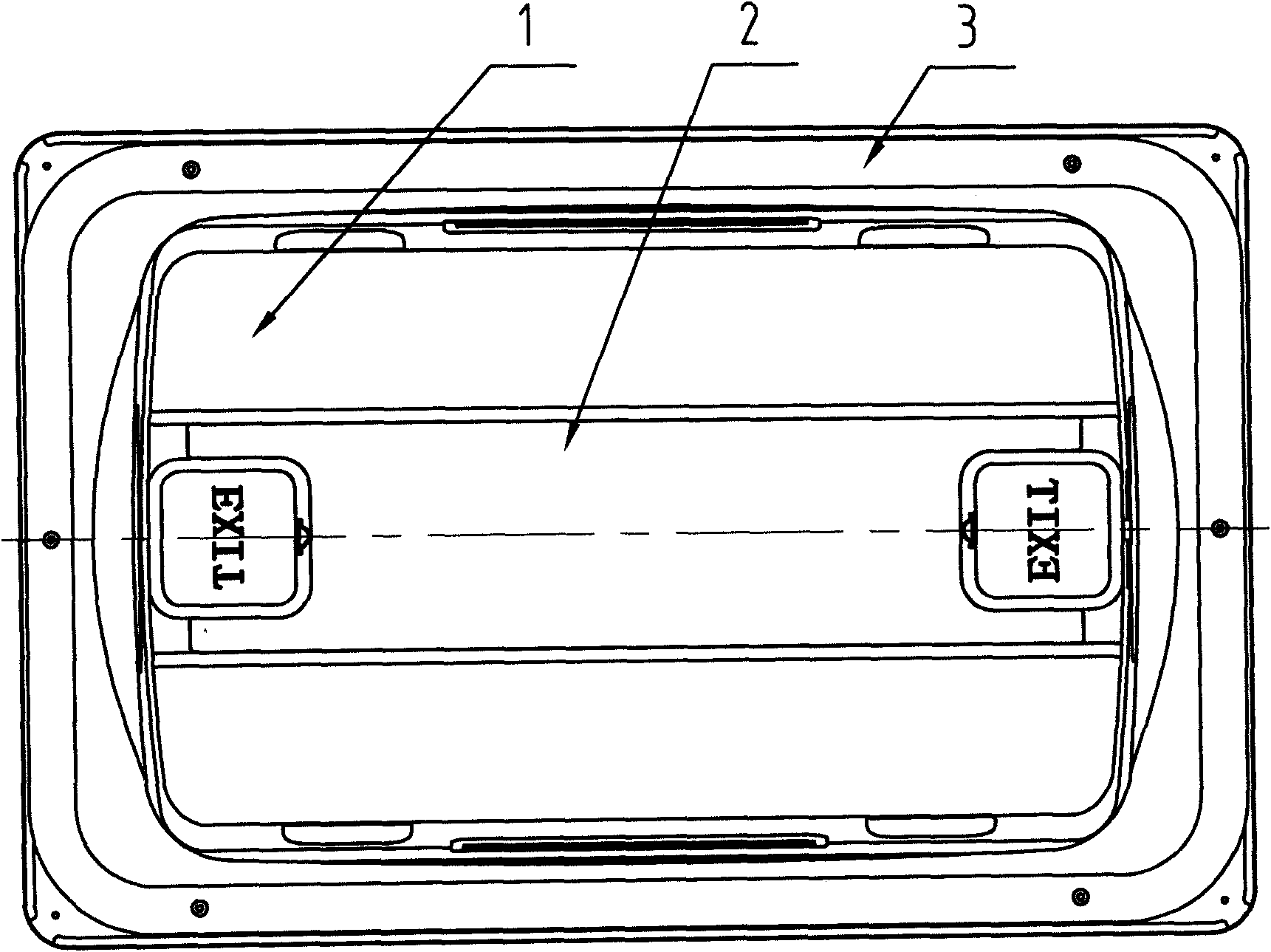
[0023] Depend on figure 1 Known, is the front view of the automobile ventilation window of the present embodiment, including the inner cover 1, the subframe 3, the decorative cover 2, and the top cover 4.

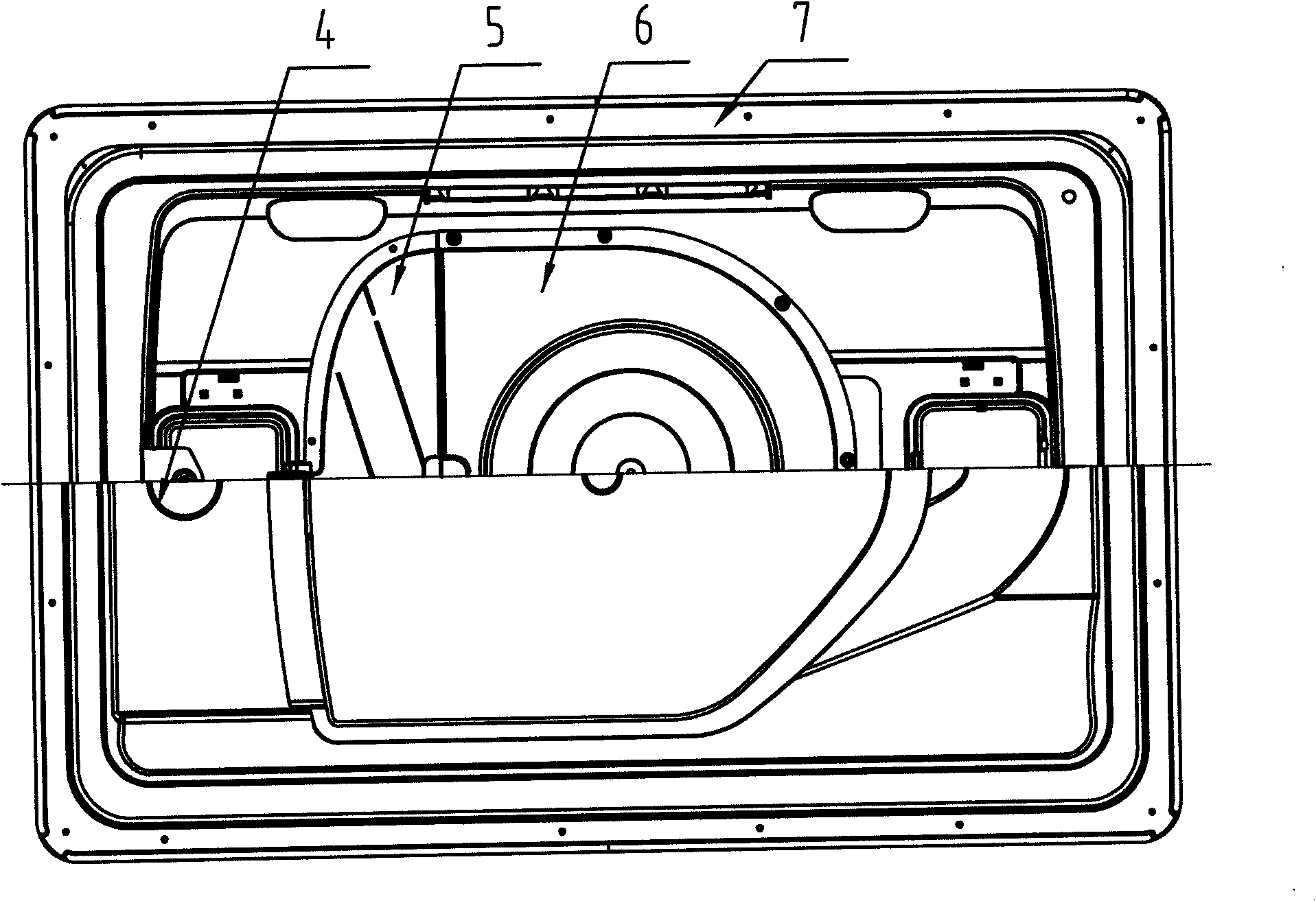
[0024] Depend on figure 2 As we know, in the rear view of this embodiment, the main frame part 9 is arranged between the sub-frame 3 and the rain cover 5, the motor is fixed in the middle of the wind guide ring 8, the sub-frame 3, the inner cover 1 and the decorative cover 2 are placed on the top. Cover the inner ring of 4.

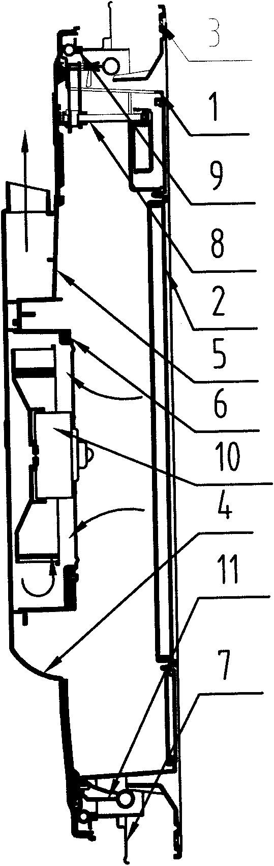
[0025] Depend on image 3 It is a schematic diagram of the structure of the rain cover 5 of the present embodiment, the push-pull device 13 and the opening device 11 are respectively fixed on the front and rear ends of the top cover 4, the rain cover 5 is fixed inside the top cover 4, and a main Frame part 9, and is fixed on the top cover 4, and the vertical direction of main frame part 9 has a straight side, and special-shaped rubber sealing ring ...


PUM


Abstract

The invention relates to an automobile air window which comprises a top cover (4), a main frame part (9), an accessory frame (3), an air guide ring (8), a ventilator (12), an inner cover (1) and a decorative shield (2), wherein a push-pull device (13) and an opening device (11) are respectively fixed at the front end and the rear end of the top cover (4); the ventilator (12) is fixed in the middleof the air guide ring (8); the accessory frame (3), the inner cover (1) and the decorative shield (2) are arranged at an inner ring of the top cover (4); rain shields (5) are fixed at both sides of the top cover (4); the main frame part (9) is arranged between the accessory frame (3) and the rain shields (5); one end of the air guide ring (8) is connected with the inner cover (1), the other end is connected with the rain shields (5), and the air guide ring (8) is fixed in the middle of the top cover (4) by the inner cover (1) to form a complete automobile air window. The structure has the functions of forced ventilation, natural ventilation and escaping and the characteristic of strong air exchange and seal.

Description

technical field [0001] The invention relates to an interior decoration of a large and medium-sized passenger car, in particular to a ventilation window of a passenger car. Background technique [0002] At present, most of the ventilation windows on automobiles and buses are of push-pull type. One push opens the ventilation window, and one pull closes the ventilation window. This kind of ventilation window is convenient to use, but there are many problems: [0003] 1. There is water leakage in the ventilation window: almost all adopt the rear direct-flow exhaust method. With this exhaust method, when the bus is running at high speed, due to the influence of the airflow, it is easy for rain to flow from the exhaust port at the rear of the sunroof. Backflow into the sunroof, causing the sunroof to leak, and seriously affecting the quality and use of the car; [0004] 2. Improper selection of skylight material: The main material used for the top cover of the ventilation window ...

Claims


Application Information

Patent Timeline
Patent Type & Authority Applications(China)
IPC IPC(8): B60J7/08B62D25/07
Inventor 张文学
Owner JIANGSU WENGUANG VEHICLE ACCESSORIES
Why Eureka
Try Eureka