Microwave oven

A technology for microwave ovens and casings, which is applied in the field of microwave ovens, and can solve problems such as reduced efficiency, affecting the normal working state of microwave ovens, and inability to cool electronic components or/and heating components, so as to achieve the effect of improving reliability

Inactive Publication Date: 2010-03-03
LG ELECTRONICS (TIANJIN) APPLIANCES CO LTD
View PDF1 Cites 0 Cited by
  • Summary
  • Abstract
  • Description
  • Claims
  • Application Information

AI Technical Summary

Problems solved by technology

[0003] However, the cooling system of the existing microwave oven cannot effectively cool the electronic components or / and heating components
Thus, affecting the normal working state of the microwave oven and reducing its efficiency

Method used


Image

  • Microwave oven
  • Microwave oven
  • Microwave oven

Examples


Embodiment Construction

[0034] Below, the microwave oven of the present invention will be described in detail with reference to the accompanying drawings and specific embodiments.

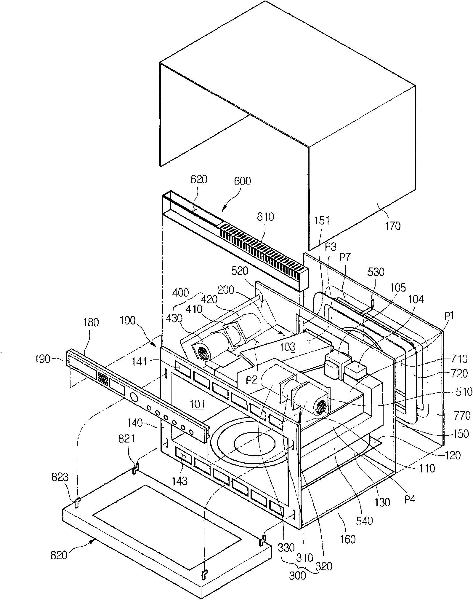
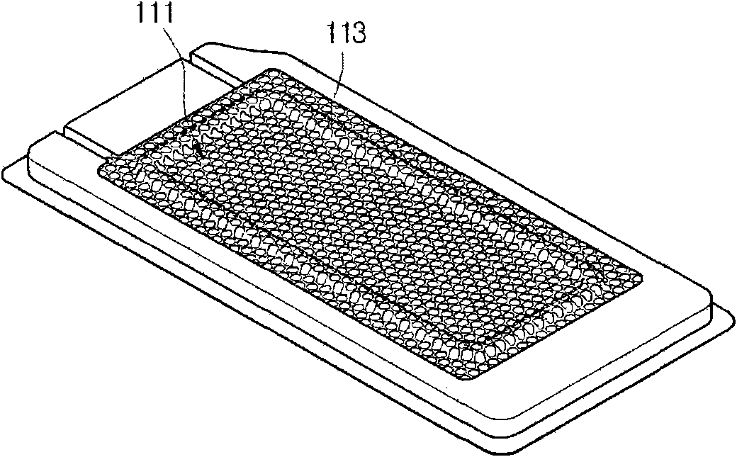
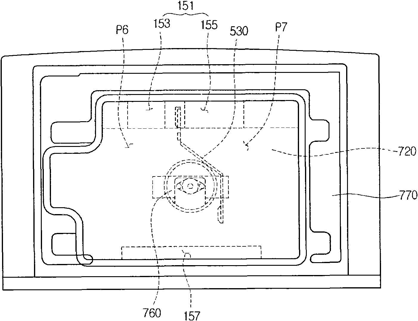
[0035] figure 1 It is a three-dimensional exploded schematic diagram of a microwave oven embodiment of the present invention; figure 2 It is a schematic diagram of the porous part of the embodiment of the present invention; image 3 It is the schematic diagram behind the embodiment of the present invention; Figure 4 It is a schematic front view of the internal structure of the convection cavity according to the embodiment of the present invention; Figure 5 yes Figure 4 The schematic diagram of the A-A' line section; Figure 6 It is a schematic side view of Embodiment 1 of the present invention; Figure 7 It is a partial structural schematic diagram including the bolt plate of the embodiment of the present invention.

[0036] Such as figure 1 As shown, the upper, lower, and two side surfaces of the housing 100 o...


PUM


Abstract

The invention discloses a microwave oven, which comprises a shell, a first fan combination, a second fan combination and a suction grating. The first fan combination is arranged on one surface of theshell, and sucks air from two sides of the shell; the second fan combination is arranged on one surface of the shell, and sucks the air from the front and the back of the shell; and the suction grating is arranged on the right front of the shell, and is provided with a suction hole for guiding the air sucked by the first fan combination and a suction opening for guiding the air sucked by the second fan combination, and the suction opening is shielded in the front of the shell. The microwave oven has the advantage that because the suction grating can prevent the air suction parts of the fan combinations from being exposed, a user can use the microwave oven more safely. Meanwhile, the fan combinations can discharge the air to the two directions of the shell at the same time, so the positionsof the parts needing to be cooled also can be diversely designed even if only the limited fan is used.

Description

technical field [0001] The invention relates to a microwave oven; in particular, to a microwave oven capable of cooling heating components more smoothly. Background technique [0002] Generally, a microwave oven is a cooking device that utilizes microwaves or / and electric heat to cook food. Such a microwave oven generally has electronic components for generating microwaves and / or electric heating components for generating electric heating; in addition, a cooling system for cooling the electronic components and / or heating components is provided in the microwave oven. [0003] However, the cooling systems of existing microwave ovens cannot effectively cool electronic components and / or heating components. Thus, the normal working state of the microwave oven is affected and its efficiency is reduced. Contents of the invention [0004] The technical problem to be solved by the present invention is to overcome the disadvantages of the prior art and provide a microwave oven cap...

Claims


Application Information

Patent Timeline
Patent Type & Authority Applications(China)
IPC IPC(8): F24C7/02F24C7/08
Inventor 金圭英陈再明金东汉崔时荣崔盛皓李尚律
Owner LG ELECTRONICS (TIANJIN) APPLIANCES CO LTD
Why Eureka
Try Eureka