
Image processing apparatus, image forming apparatus and image processing method

An image processing device, image display device technology, applied in the direction of image communication, electrical components, etc., can solve the problems of image color inconsistency, correction processing not recorded, color difference, etc.

Inactive Publication Date: 2010-03-03
SHARP KK
View PDF3 Cites 3 Cited by
  • Summary
  • Abstract
  • Description
  • Claims
  • Application Information

AI Technical Summary

Problems solved by technology

[0007] In the above-mentioned Patent Document 1, it is described that a monochrome image is previewed, but there is no description about the correction process when displaying the monochrome image data on a display device.
Therefore, there will be a problem that the color of the printed image does not match the color of the image displayed on the display device.
In addition, in the above-mentioned Patent Document 2, there is no description about displaying the read image data in one-color or two-color, but there are the following problems when performing preview display in one-color or two-color
The first problem is that although it is described that as a masking / UCR circuit, a CMYK signal is generated by a 4×8 matrix operation considering a quadratic term, and in the inverse masking circuit, an inverse transformation is performed by a 3×4 matrix operation, but in In the above method, the color difference will become larger
Therefore, there will be a problem that the color of the printed image does not match the color of the image displayed on the display device.
The second problem is that since the image processing circuit for preview is provided with an inverse masking circuit, an inverse logarithmic conversion circuit, and a 3×3 matrix conversion circuit in addition to the image processing circuit for printing processing, the circuit scale increases.
[0008] As described above, in the prior art, when printing in one color or two colors, the color of the image displayed in the preview is different from the color of the image actually printed, and there are problems that the scale of the circuit increases.

Method used


Image

  • Image processing apparatus, image forming apparatus and image processing method
  • Image processing apparatus, image forming apparatus and image processing method
  • Image processing apparatus, image forming apparatus and image processing method

Examples


Embodiment approach 1

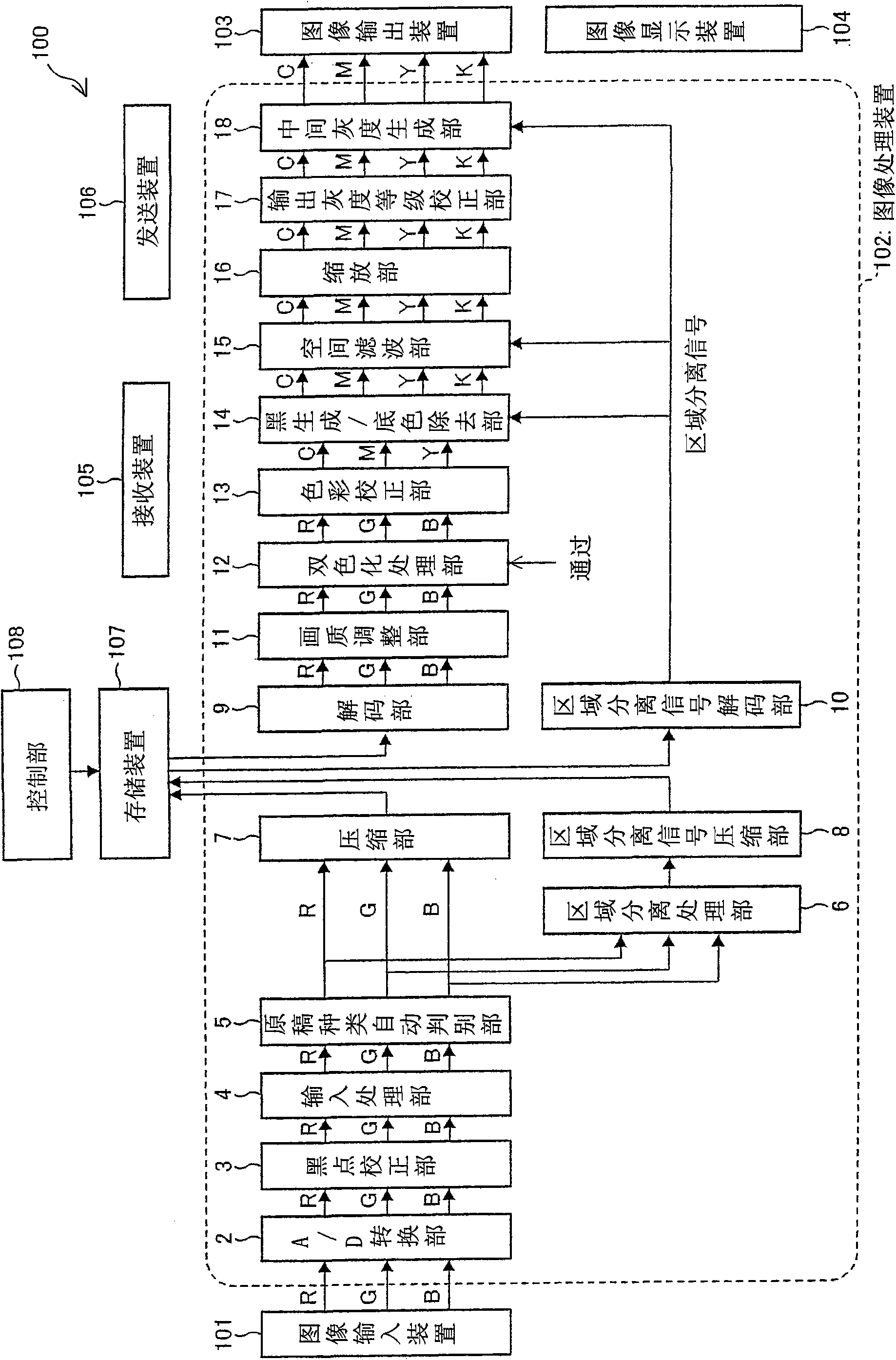
[0034] One embodiment of the image forming apparatus of the present invention will be described with reference to the drawings. figure 1 It is a block diagram showing a schematic configuration of the image forming apparatus 100 according to this embodiment.

[0035] The image forming apparatus 100 of this embodiment is a digital color multifunction peripheral that executes the selected mode when any one of the copier mode, print mode, facsimile transmission mode, facsimile reception mode, and image transmission mode is selected.

[0036]The copier mode (copier mode) refers to a mode in which image data is read (original document is read to generate image data), and an image of the image data is printed on paper. Note that the print mode refers to a mode in which an image of image data transmitted from a terminal device connected to image forming apparatus 100 is printed on paper. The facsimile transmission mode refers to a normal facsimile mode in which image data obtained by...

Embodiment 1

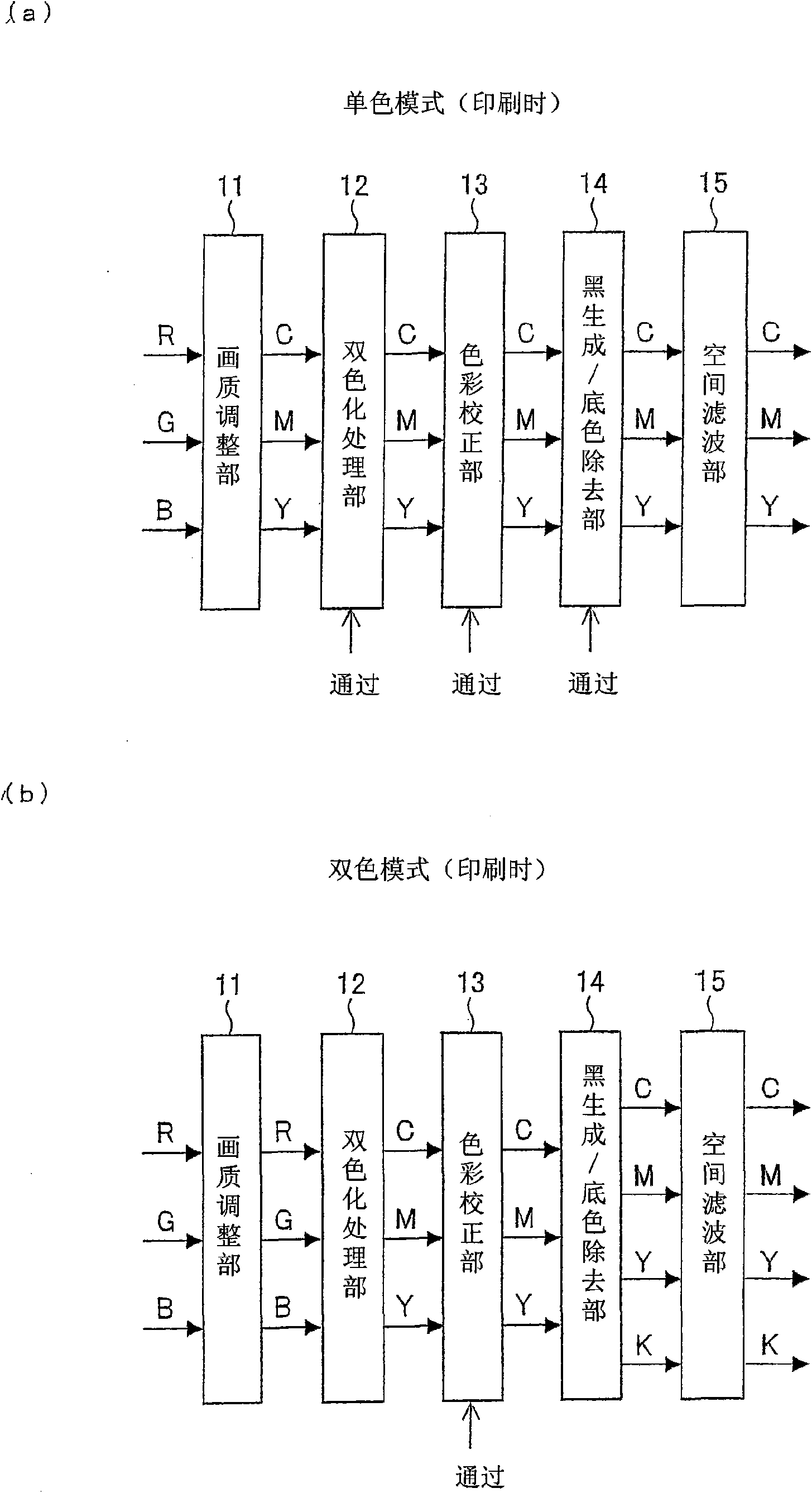
[0077] The two-color processing section 12 is under the situation of selecting the two-color mode, such as figure 2 As shown in (b), a block that converts RGB image data output from the image quality adjustment unit 11 into CMY image data is performed. In addition, conversion processing from RGB image data to CMY image data in the two-color mode can be realized by, for example, the method of [Example 1] or [Example 2] described in JP-A-2007-28336.

[0078] In addition, the two-color processing unit 12, in the case of selecting the full-color mode, as figure 1 As shown, the RGB image data output from the image quality adjustment unit 11 is not processed at all, and the image data is directly transmitted (passed) to the color correction unit 13 . In addition, when the two-color processing unit 12 selects the monochrome mode, as figure 2 As shown in (a), the CMY image data output from the image quality adjustment unit 11 is not processed at all, and the image data is directly...

Embodiment approach 2

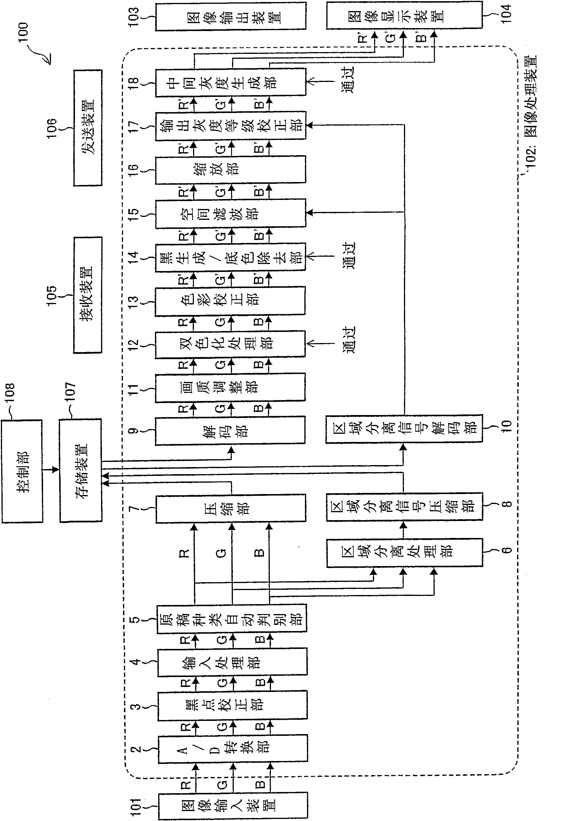
[0177] In this embodiment, when printing in one color or two colors, processing is performed to reduce the difference between the color of an image displayed as a preview and the color of an image actually printed. This processing will be described in detail below. The configuration of the image processing device of the present embodiment is the same as that of the image processing device 102 of the first embodiment.

[0178] (1) At the time of printing processing

[0179] (1-1) Monochrome mode

[0180] When the monochrome mode is selected, the image data is converted into monochrome image data (monochrome image data, converted image data) by the image quality adjustment unit (color conversion unit) 11 using the above formula 1 as in the first embodiment. In addition, the following formula 3 is used when the vividness is adjusted by the image quality adjustment unit 11 . The parameters r1' to r3' and a11 to a33 use different parameters from the parameters when converting to...


PUM


Abstract

The invention provides an image processing apparatus, an image forming apparatus and an image processing method. The image processing apparatus of the present invention includes a color matching section for performing, on monochrome or two-color image data to be supplied to an image display device, a color matching process of reducing differences in color from a single- or two-color image to be outputted by an image display device, and as such, can display a comfortable preview of a single- or two-color image data by reducing differences in color between an image to be previewed and an image to be actually printed.

Description

technical field [0001] The present invention relates to an image processing device, an image forming device, an image processing method, and a computer-readable recording medium for displaying thumbnails or previews of input image data. Background technique [0002] In image forming devices such as copiers and MFPs, there is image data that has been processed based on document types and setting conditions (print density, zoom ratio, single-sided printing or double-sided printing, margin size, etc.) , a device that previews and displays images of printing objects page by page, or synthesizes images of multiple printing objects and displays them in preview. [0003] Regarding such a preview display, for example, Patent Document 1 describes that it includes a monochrome image that is composed of only one color (a monochrome image such as a document or a monochrome image composed of a single color such as an advertisement) that is copied. A color mode and a mode for copying a f...

Claims


Application Information

Patent Timeline
IPC IPC(8): H04N1/60
CPCH04N1/6011H04N1/60
Inventor 南雅范后藤牧生
Owner SHARP KK
Learn More