
Method and device for adjusting camera system

A technology of camera system and equipment, applied in the field of image processing, to achieve the effect of reducing complexity, speeding up adjustment speed and reducing workload

Active Publication Date: 2010-03-03
LENOVO (BEIJING) CO LTD
View PDF0 Cites 16 Cited by
  • Summary
  • Abstract
  • Description
  • Claims
  • Application Information

AI Technical Summary

Problems solved by technology

[0005] The purpose of the embodiments of the present invention is to solve the problem of how to confirm and adjust the best viewing area when more than two camera units capture images

Method used


Image

  • Method and device for adjusting camera system
  • Method and device for adjusting camera system
  • Method and device for adjusting camera system

Examples


Embodiment Construction

[0026] Detailed reference is now provided to embodiments of the invention. The following embodiments will be described in order to explain the present invention by referring to the figures.

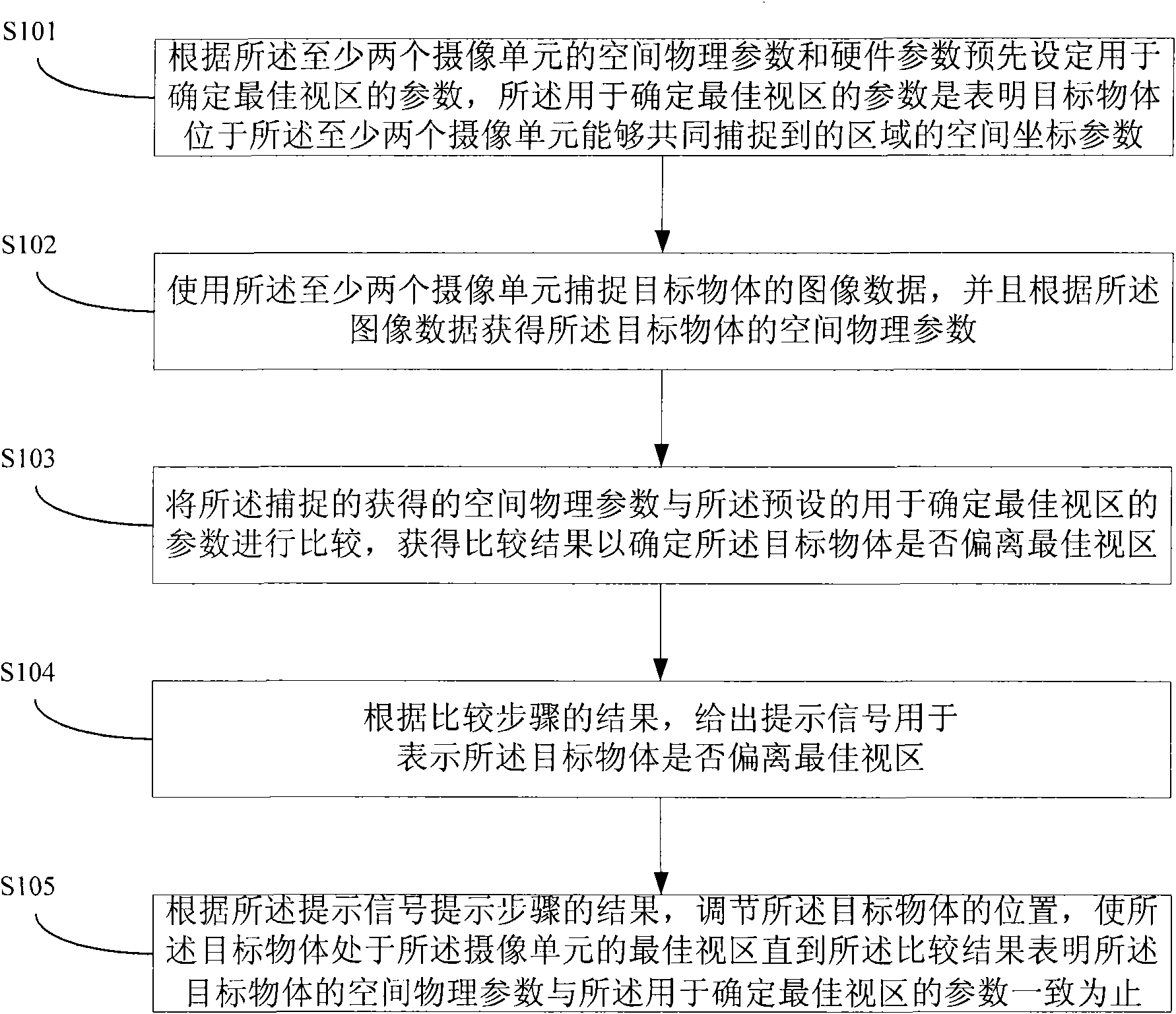
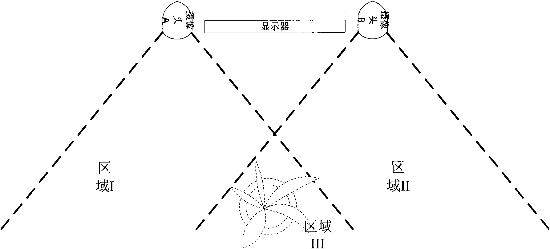
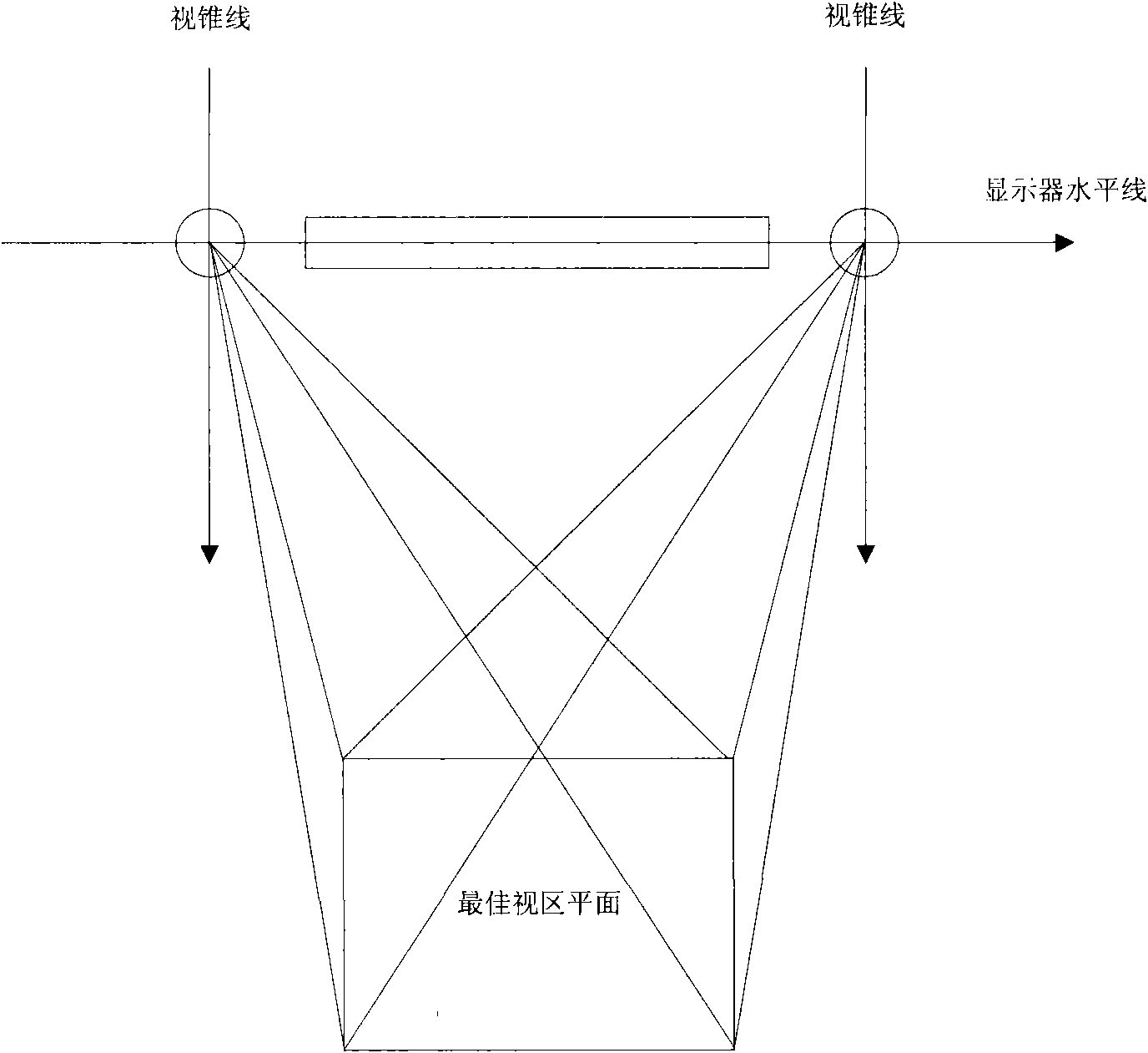
[0027] figure 1 A flowchart of a method for adjusting a camera system according to an embodiment of the present invention is shown. Such as figure 1 As shown, the camera system includes at least two camera units, and the method includes the following steps: Preset step S101, according to the spatial physical parameters and hardware parameters of the at least two camera units, preset for determining the best viewing angle The parameters of the area, the parameters used to determine the best viewing area are the spatial coordinate parameters that indicate that the target object is located in the area that the at least two camera units can capture together; the capturing step S102, using the at least two camera units Capture the image data of the target object, and obtain the spatial phys...


PUM


Abstract

The invention relates to a method and a device for adjusting a camera system. The method comprises the following steps of: presetting parameters for determining an optimal visual area according to spatial physical parameters and hardware parameters of camera units, wherein the parameters for determining the optimal visual area indicate that a target object is positioned in an area which can be captured by at least two camera units; capturing image data of the target object by the camera units, and acquiring spatial parameters of the target object according to the image data; comparing the acquired spatial parameter with the preset parameters for determining the optimal visual area so as to determine whether the target object deviates from the optimal visual area; giving a prompting signalto indicate whether the target object deviates from the optimal visual area; and adjusting the position of the target object according to the prompting signal until the spatial physical parameters ofthe target object is in accordance with the parameters for determining the optimal visual area. The method and the device provided by the embodiment of the invention provide helps for adjusting the target object to enter the optimal visual area through an interactive prompting means.

Description

technical field [0001] The invention relates to the field of image processing, in particular to a method and equipment for adjusting a camera system. Background technique [0002] Cameras have become one of the necessary input devices for current computers. At present, cameras are mainly used in video chatting. However, Vimicro has demonstrated more camera-based applications to the industry, such as: face tracking, face recognition (can be used for video surveillance, check-in system, human-computer interaction, system boot), face 3D animation, QR code Information reading (reading two-dimensional code business cards, reading two-dimensional codes of URLs, telephone and mail information), video surveillance, etc. [0003] However, the above applications are still based on the use of a single camera. If a computer is compared to a human brain, then a camera is similar to a human eye. A single camera is monocular, while dual cameras are binocular. In addition, to input 3D ...

Claims


Application Information

Patent Timeline
IPC IPC(8): H04N17/00
Inventor 姜珊
Owner LENOVO (BEIJING) CO LTD
Learn More