
Adaptive automatic dimming photoelectric device

A photoelectric device and natural light technology, applied in the direction of lighting devices, lamp circuit layout, light source, etc., can solve the problems of inaccurate system control, system instability, affecting use, etc., achieve flexible configuration, wide adaptability, and energy saving effects

Inactive Publication Date: 2010-03-03
刘红超
View PDF0 Cites 22 Cited by
  • Summary
  • Abstract
  • Description
  • Claims
  • Application Information

AI Technical Summary

Problems solved by technology

However, in other lighting applications, such as street lamps, household lighting, and factory lighting, due to the interaction between the light-emitting device itself and the natural light in the environment, the system control is not accurate, and even the system is unstable, which affects the use.
In order to eliminate the mutual interference between natural light and light-emitting devices, a complex algorithm system is required, which is costly and can only be used for large-scale lighting such as offices and factories that can afford the system cost.

Method used


Image

  • Adaptive automatic dimming photoelectric device
  • Adaptive automatic dimming photoelectric device
  • Adaptive automatic dimming photoelectric device

Examples


Embodiment 1

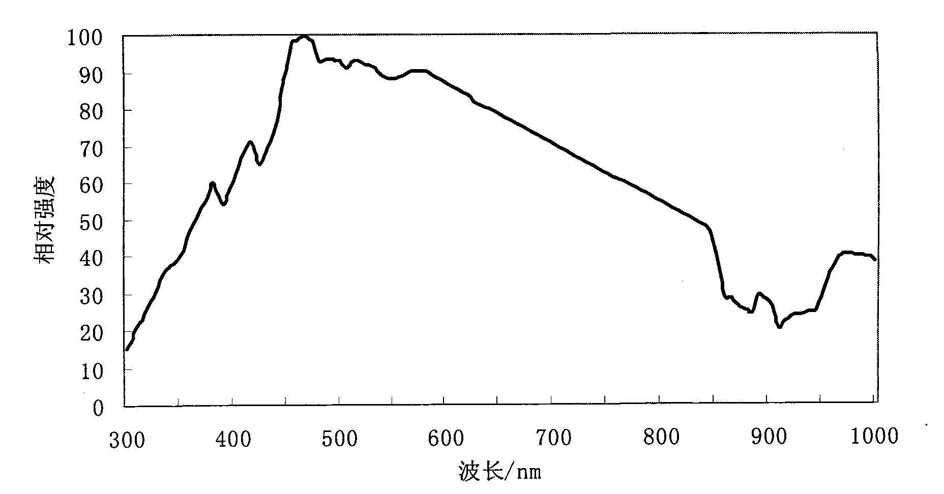
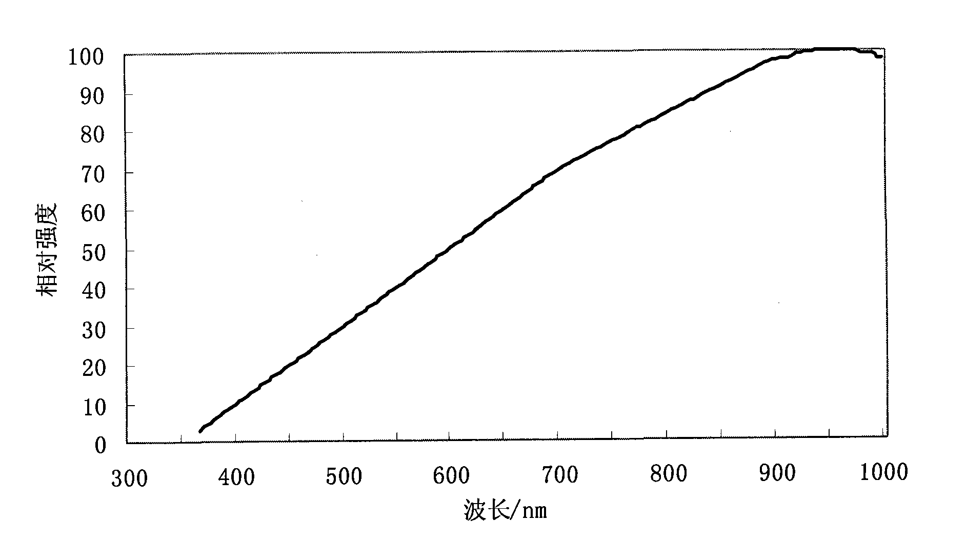
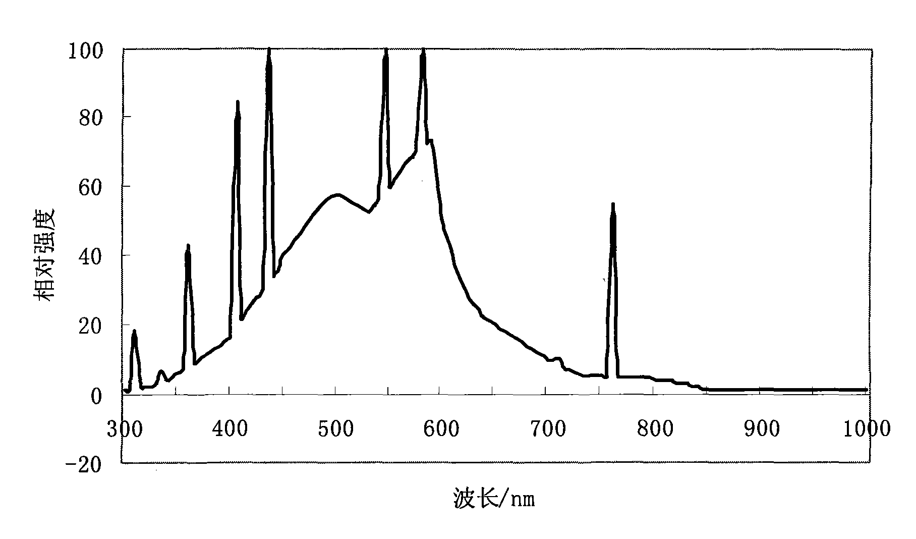
[0036] image 3 It is the implementation of adaptive self-dimming method in PWM dimming LED lighting. image 3 Middle 1 is a phototransistor with a color filter, where the color filter acts as a wavelength selection unit, and the photodiode acts as a photoelectric sensing unit. The device 2 indicated by the dotted line box functions as an electrical signal conversion unit, including an amplifier and 21 . In digital type control, 21 can be an analog-to-digital (A / D) converter or MCU, and in analog control, it can be a simple inverter. 3 is an LED light emitting device. 4 is a PWM controller, and 6 feedback resistors (playing the role of a threshold adjustment unit) together play the role of a light source brightness control unit. 5 is the power supply, which can be a single battery or a DC power supply, or an AC power supply. After conversion, it can supply power to each device in the figure according to the needs; for the power supply of the PWM dimming LED, an auxiliary st...

Embodiment 2

[0041] See also for the realization of adaptive self-dimming method in LED analog dimming lighting image 3 . The signal acquisition method is the same, but the control method is slightly different. In analog control, 21 can be turned into a simple inverter. The purpose of using 21 inverters is to provide a stable negative feedback to the system, that is, the stronger the natural light, the lower the output voltage. Use its output voltage as a reference voltage source for the feedback resistor of the PWM controller, the lower the voltage, the smaller the current applied to the feedback resistor, and the darker the LED. This realizes a stable adaptive dimming system.


PUM


Abstract

The invention designs an adaptive automatic dimming photoelectric device. The device consists of the following main modules: a power supply, a waveband selection unit, a photoelectric sensing unit, an electrical signal conversion unit, a light source brightness control unit, a threshold adjustment unit and a luminous unit. Based on characteristic wave spectrum of a light source, the device can simply judge which sources the detected light intensity and color signals are from so as to control whether a luminous device is luminous or luminous strength or color characteristics and the like simply according to the brightness and chromatographic characteristics of natural light. The photoelectric device of the invention has the advantages of simple structure, flexible deployment and wide adaptive range. The system can be used for small-area single lamp illumination, also can be used for illumination for large-area offices, plants, street lamps, public places and the like, and further can be used for special illumination places such as color atmosphere decoration, backlight illumination and the like so as to make full use of the natural light and save energy.

Description

technical field [0001] The present invention relates to photoelectric control technology, in particular to the automatic control technology of luminous brightness, especially to automatically adjust the luminous intensity of light-emitting devices according to the brightness of natural light in the environment, which is suitable for daily lighting and backlighting of solid luminescence and gas luminescence. Decorative lighting, automotive lighting, information display, logo display, optical communication and various special lighting and display fields. Background technique [0002] Today, people are paying more and more attention to energy. In addition to finding low-cost renewable new energy sources, the development of energy-saving technologies for the use of existing energy sources is also of concern to governments and the public. The former is open source, which is easy to attract people's attention; while the latter is throttling, which is often not enough attention. L...

Claims


Application Information

Patent Timeline
Patent Type & Authority Applications(China)
IPC IPC(8): H05B37/02H05B39/04H05B41/36
CPCY02B20/14Y02B20/40Y02B20/46Y02B20/00
Inventor 刘红超
Owner 刘红超
Learn More