Chisel holder

A tool holder and tool technology, used in cutting machinery, earth-moving drilling, slitting machinery, etc., can solve problems such as unevenness, influence of tool rotation performance, and the central longitudinal axis of the tool holding device cannot be vertical, etc., and achieves easy manufacturing. The effect of stable and reliable arrangement

Active Publication Date: 2010-03-10
WIRTGEN GMBH
View PDF7 Cites 17 Cited by
  • Summary
  • Abstract
  • Description
  • Claims
  • Application Information

AI Technical Summary

Problems solved by technology

Its disadvantage is that it produces an uneven surface which is not exactly perpendicular to the central longitudinal

Method used


Image

  • Chisel holder
  • Chisel holder
  • Chisel holder

Examples


Embodiment Construction

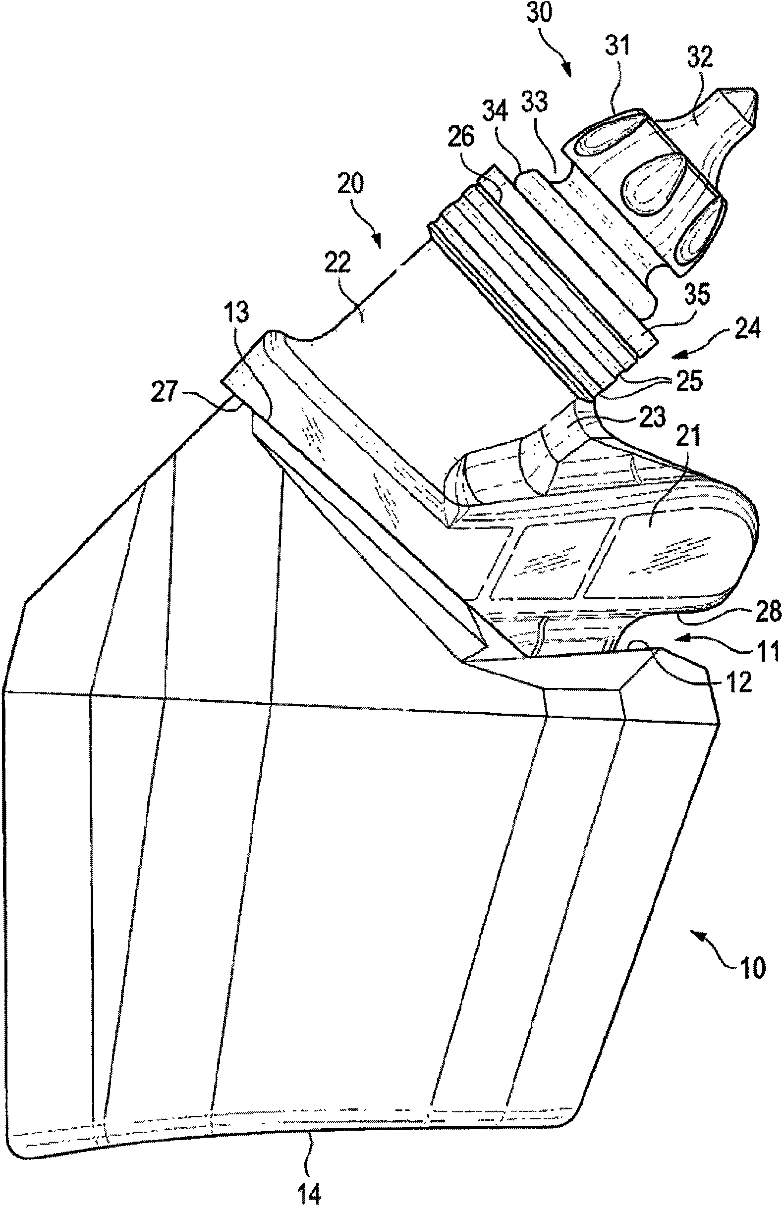
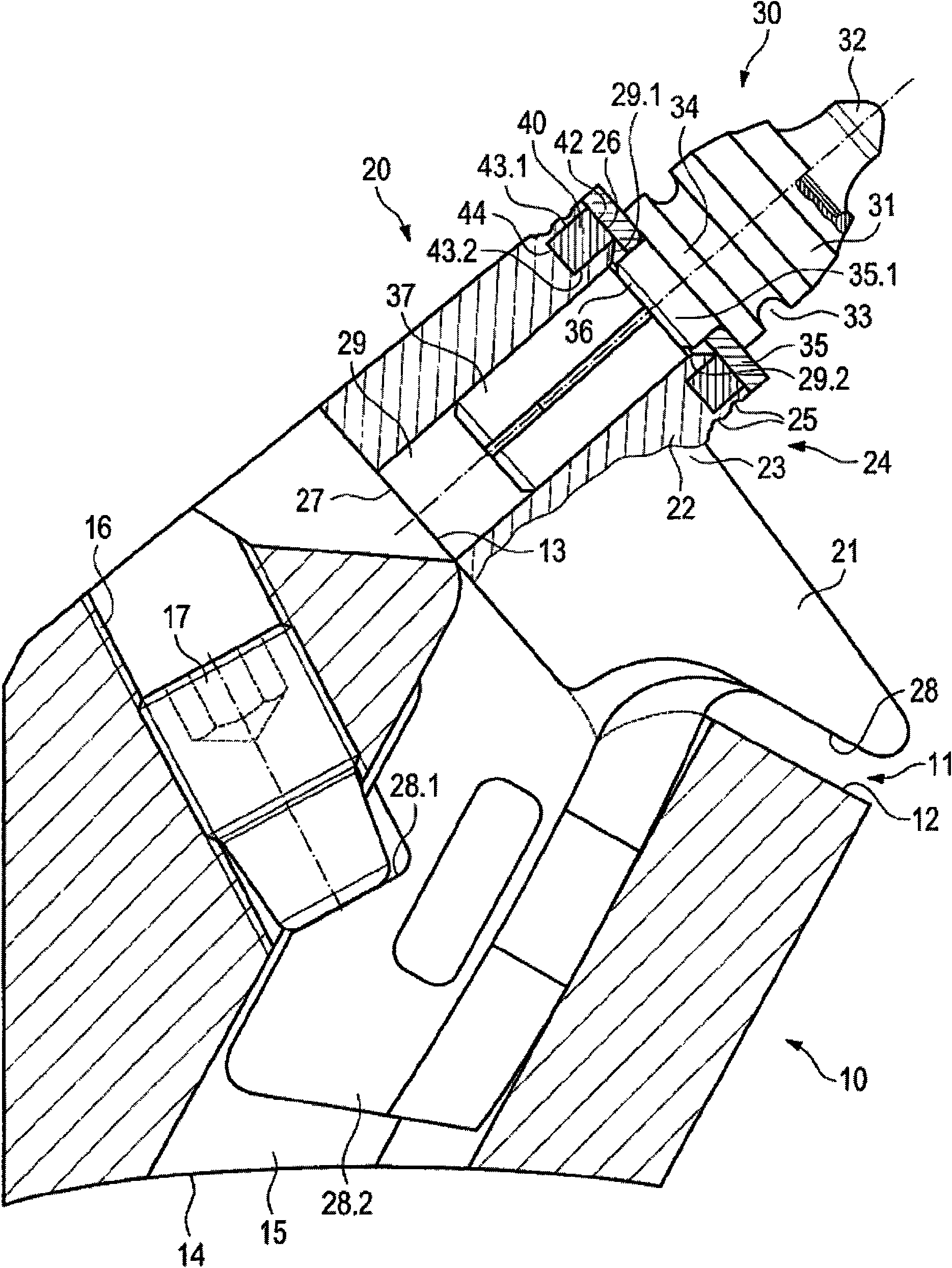
[0028] figure 1 and figure 2 A tool holder changing system is described which has a base 10 , a tool holder 20 and a tool 30 .

[0029] Such as figure 2 As shown, the base 10 has a shank holder 15 which is formed in the base 10 in the form of a through-hole starting from the shoulder 12 or the base 14 .

[0030] The stop surface 13 is connected at an angle to the shoulder 12 . The base 10 can be mounted via a bottom surface 14 on the outer circumference of a road milling machine milling drum (not depicted in the figures). The base 10 is welded to the milling drum. A threaded hole 16 leads into the tool shank holding device 15 in the opposite direction of tool feed, into which a set screw 17 is screwed.

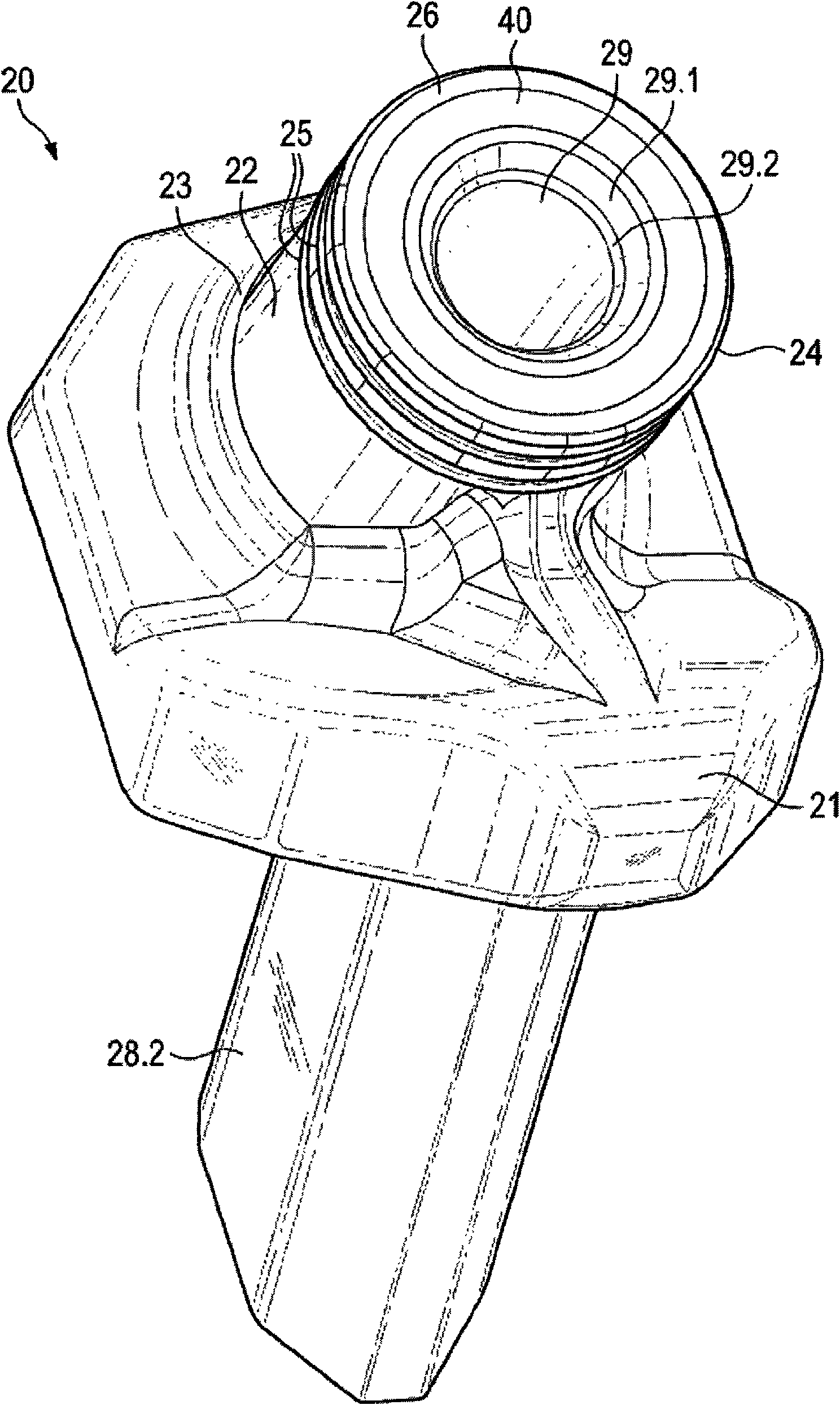
[0031] The fixing screw 17 is used to fix the knife seat 20. The knife holder 20 has a baffle 21 which is connected with a connecting section 23 . The connecting section 23 supports an additional part 22 which has a cylindrical section 24 extending beyond the stop 23 ...


PUM


Abstract

The invention relates to a chisel holder for a cutting machine, road milling machine, surface miner, or the like, having a chisel receptacle, which comprises an insertion opening, and having a chiselsupporting surface, wherein at least one wear protection element is arranged in an area associated with the chisel supporting surface. In order to bring about effective wear protection in such a chisel holder at low cost, it is provided that the at least one wear protection element is designed as a weld and is arranged at least in areas in at least one opening.

Description

technical field [0001] The present invention relates to a tool block for coal cutters, road milling machines, surface mining machines or similar machines, which has a tool holding device with a socket and a tool support surface, while in a piece belonging to the tool At least one wear protection element is installed in the region of the support surface. Background technique [0002] Such a seat is known from US 6,585,327 B2. The tool holder now has a bore as a tool holder. Replaceable knives can fit inside. In each case a counterbore is provided in the region of the hole entry, into which a carbide ring is welded. The tool holder is now aligned with the center of the hole through the carbide ring. The tool inserted into the tool holder is supported with its tool tip on a tool support surface of the facing away from the carbide ring. [0003] At the same time, two carbide rings also support the tool in the handle part and play a role in preventing wear during use. The u...

Claims


Application Information

Patent Timeline
IPC IPC(8): E21C35/18
CPCE21C35/183E21C2035/1813E21C2035/1806E21C35/1831E21C35/1835
Inventor 托马斯·莱纳特克里斯蒂安·贝尔宁马丁·伦茨
Owner WIRTGEN GMBH
Why Eureka
Try Eureka