
LED lamp with heat dissipation device and manufacturing method thereof

A technology of LED lamps and cooling devices, which is applied in the parts of lighting devices, damage prevention measures of lighting devices, cooling/heating devices of lighting devices, etc., which can solve the problems of harsh outdoor environments, limited use occasions, and different technical solutions problems, to achieve the effect of increased heat dissipation area, flexible installation and use, and efficient heat dissipation

Active Publication Date: 2012-10-03
杭州西子孚信科技有限公司
View PDF5 Cites 1 Cited by
  • Summary
  • Abstract
  • Description
  • Claims
  • Application Information

AI Technical Summary

Problems solved by technology

[0004] 1. The heat sink technology commonly used in existing LED street lamps is not mature enough. Low-end heat sinks are rough in manufacture and poor in heat dissipation, and cannot achieve the purpose of rapid heat conduction; high-end heat sinks are too expensive and limited in use. Although the heat dissipation effect is good, it is not suitable for street lamps used in the open air
[0005] 2. The known finned radiators are air-cooled or water-cooled. These radiators are not suitable for street lamps
[0006] 3. Although the heat dissipation effect of the known heat pipe radiator is relatively good, but due to the greatly increased cost, and the harsh outdoor environment, the heat pipe is easily damaged, so the use is also limited
[0007] 4. The structure of the real radiator cannot be matched and installed with other modules in the lamp body of the real street lamp, so it is impossible to achieve the optimal heat dissipation effect
[0008] After retrieving Chinese patents, there are several articles on the invention of LED lamps with heat sinks, but they are different from the technical solutions provided by the present invention; they do not involve the processing method of the present invention, and so far, the prior art does not relate to the present invention. invention related technology

Method used


Image

  • LED lamp with heat dissipation device and manufacturing method thereof
  • LED lamp with heat dissipation device and manufacturing method thereof
  • LED lamp with heat dissipation device and manufacturing method thereof

Examples


Embodiment Construction

[0049] specific implementation plan

[0050] The detailed technical contents and embodiments of the present invention will be further described below in conjunction with the accompanying drawings.

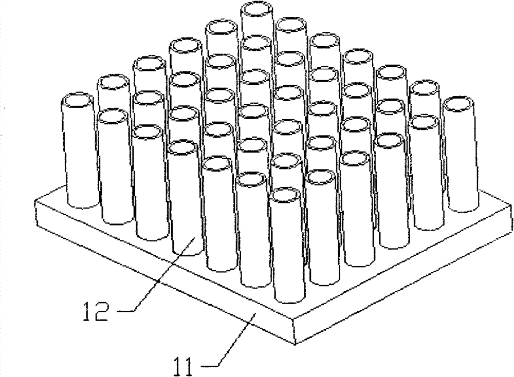
[0051] attached figure 1 It shows a three-dimensional schematic view of Embodiment 1 of the middle piece 1 chimney radiator of the present invention, wherein the cooling handles 12 are all hollow cylinders on the base 11 .

[0052] It should be noted that the heat dissipation rod 12 under the present invention can also be in the shape of a cone or other polygonal geometry, but usually the small end of the cone-shaped heat dissipation rod is arranged upwards and the large end is downwards.

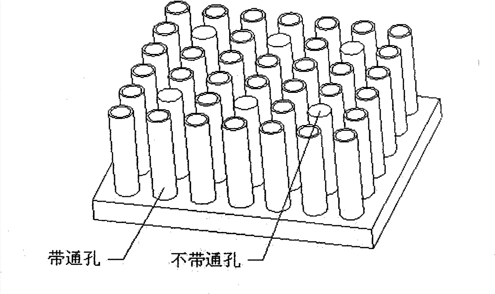
[0053] attached figure 2 It is a three-dimensional schematic diagram of the second embodiment of the middle part 1 of the present invention, wherein a part of the cooling rod 12 is a hollow cylinder, and the other part is solid, and they are also arranged on the base 11. The hollow cooling ro...


PUM


Abstract

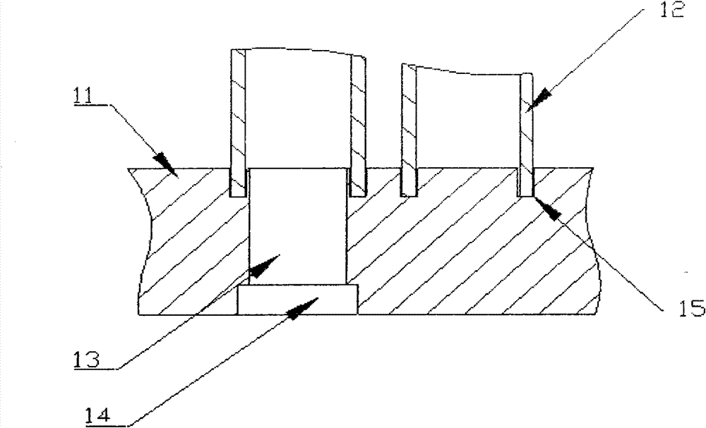
The invention relates to an LED lamp with heat dissipation device and a manufacturing method thereof. The device comprises a heat dissipater 1, an LED light source module 2 fixed on the heat dissipater 1, as well as a photo-permeable board 4 and a lamp holder shell 5, and is connected with power supply 6, wherein the heat dissipater 1 is of a chimney-shaped heat dissipating structure, the heat dissipater 1 is constructed by a seat 11 and a plurality of chimney-shaped heat dissipating rods 12 arrayed on the seat 11, the seat is provided with through holes 13, the hollow heat dissipating rods 12 are mounted at the position corresponding to the through holes 13, the LED light source module 2 is constructed by a substrate 21 provided with a printing circuit, a plurality of LED particles 22 welded and fixed on the substrate 21, and an LED light distributing lens 23. The invention fills the blank of the prior art, the device has quick and efficient heat dissipation effect, and features simple structure, distinctive design, good airtightness, high commonality, flexible mounting and using, convenient maintenance and low cost.

Description

technical field [0001] The invention relates to an LED lamp with a cooling device and a processing method thereof, which belongs to the technical field of LED lighting and is especially suitable for street lamps. Background technique [0002] The lamp cap of a known LED street lamp is composed of LED particles, a circuit, a light source module equipped with a lens, a heat sink, a lamp housing and a power supply, wherein the light source and power supply are generally integrated in a relatively closed lamp housing. Because it is used as a street light, high-power LEDs are usually required, and high-power LEDs will emit a lot of heat when they work. If the heat cannot be discharged in time, the temperature of the PN junction of LED particles will increase significantly, which greatly affects the service life of LEDs. And color rendering, these heats also have a negative impact on the power supply, therefore, how to quickly and efficiently export the heat generated by LED parti...

Claims


Application Information

Patent Timeline
Patent Type & Authority Patents(China)
IPC IPC(8): F21S2/00F21V29/00F21V19/00F21V23/00F21V17/00F21V5/00F21V5/04F21V15/02F21Y101/02F21K9/20F21K9/69F21K9/90F21V29/80F21Y115/10
Inventor 陈凯章子奇赵雅杰陈林陈鹏
Owner 杭州西子孚信科技有限公司
Learn More