Exhaust recovery device of deaerator

An exhaust gas recovery and deaerator technology, applied in liquid degassing, chemical instruments and methods, separation methods, etc., can solve the problems of unutilized steam heat, increased atmospheric emissions, environmental thermal pollution, etc., and achieve energy-saving effects The effect of obvious, protecting the environment and eliminating air pollution

Active Publication Date: 2010-03-10
HUAQIANG CHEM GRP
View PDF0 Cites 2 Cited by
  • Summary
  • Abstract
  • Description
  • Claims
  • Application Information

AI Technical Summary

Problems solved by technology

This deaeration method has the advantages of simplicity, reliability and good deaeration effect, but the steam generated by the deaerator is generally discharged directly into the atmosphere, which not only increases the amount of atmospheric emissions and causes thermal pollution to the environment, but also of heat is not used, wasting energy

Method used


Image

  • Exhaust recovery device of deaerator

Examples


Embodiment Construction

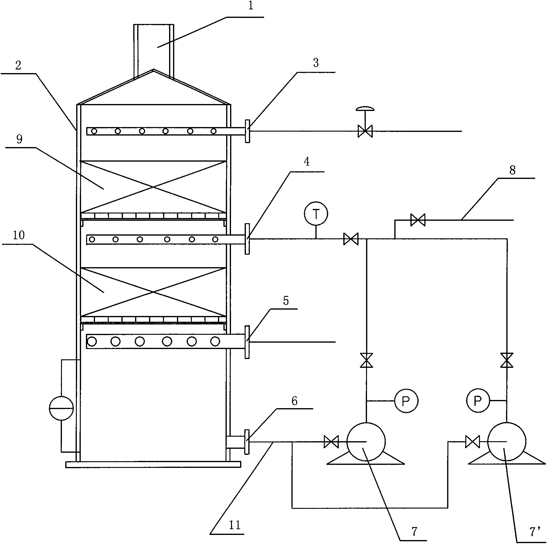
[0010] Such as figure 1 As shown, the present invention includes a packed tower shell 2, the filler in the packed tower shell 2 is divided into an upper packing layer 9 and a lower packing layer 10, the top of the packed tower shell 2 is provided with an exhaust port 1, and the packed tower shell 2 The upper part is provided with a cold water inlet 3, the lower part of the packed tower shell 2 is provided with a steam inlet 5 and a hot water outlet 6 in sequence, and the circulating hot water inlet 4 is arranged on the packed tower shell 2 between the upper packing layer 9 and the lower packing layer 10 , one end of the water outlet pipe 11 communicates with the hot water outlet 6, the other end of the water outlet pipe 11 communicates with the inlets of the two water pumps 7, 7' respectively, the outlets of the two water pumps 7, 7' communicate with the circulating hot water inlet 4, and the two water pumps The pipeline between 7 and 7' communicates with the water inlet pipe ...


PUM


Abstract

An exhaust recovery device of a deaerator comprises a packing tower shell body, wherein the packing in the packing tower shell body is divided into an upper packing layer and a lower packing layer; the top part of the packing tower shell body is provided with an exhaust port; the upper part of the packing tower shell body is provided with a cold water inlet; the lower part of the packing tower shell body is provided with a steam inlet and a hot water outlet; a circulating hot water inlet is arranged on the packing tower shell body between the upper packing layer and the lower packing layer; one end of a water outlet pipeline is communicated with the hot water outlet and the other end of the water outlet pipeline is respectively communicated with the inlets of two water pumps; the outlets of two water pumps are communicated with the circulating hot water inlet; the pipeline between two water pumps is communicated with the water inlet pipe of the deaerator; the upper packing layer and the lower packing layer are structured packing layers; and the water pumps are centrifugal pumps. The exhaust recovery device of the deaerator can recover and utilize the heat in the steam which is exhausted by the deaerator, reduces the atmospheric emissions, saves the energy, protects the environment, and has simple structure and convenient use.

Description

technical field [0001] The invention relates to a boiler heat recovery device, in particular to a deaerator exhaust gas recovery device. Background technique [0002] In the production process of industrial enterprises with boilers and electric power enterprises, the deaeration method of boiler feed water usually adopts thermal deaeration method to ensure the quality of feed water. This deaeration method has the advantages of simplicity, reliability and good deaeration effect. However, the steam generated by the deaerator is generally discharged directly into the atmosphere, which not only increases the amount of atmospheric emissions and causes thermal pollution to the environment, but also The heat is not used, wasting energy. According to calculations, an atmospheric deaerator with an output of 100 tons, under normal operating conditions, when the water temperature in the deaerator reaches 104°C and the pressure in the deaerator reaches above 0.02MPa, the amount of steam...

Claims


Application Information

Patent Timeline
Patent Type & Authority Applications(China)
IPC IPC(8): F22D1/50
Inventor 余华强
Owner HUAQIANG CHEM GRP
Why Eureka
Try Eureka