Conductance and differential conductance synchronous measuring device and method

A technology of differential conductance and synchronous measurement, which is applied in the direction of measuring devices, measuring electrical variables, measuring resistance/reactance/impedance, etc. It can solve the problems of affecting the measurement results of conductance, difficulty in making devices, and low precision of voltage source meters.

Inactive Publication Date: 2010-03-10
NANCHANG HANGKONG UNIVERSITY
View PDF1 Cites 3 Cited by
  • Summary
  • Abstract
  • Description
  • Claims
  • Application Information

AI Technical Summary

Problems solved by technology

The usual method is to measure the current-voltage relationship, and then perform numerical differentiation to obtain the conductance [(Thomas D.E., et al.. Rev Sci Ins, 1963.34 (8): 920), (William R, et al.. Rev Sci Ins, 1964.35( 12): 1704)], but due to the low accuracy of the voltage source meter, and the jump point will occur when changing the range, which seriously affects the conductance measurement result
There is also the use of lock-in amplification technology [Huang Zhiyao, etc., liquid conductance measuring device with adjustable working frequency, utility model patent number: CN2814424Y] to realize conductance signal measurement, but the conductance measurement circuit board is very complicated, and there are difficulties in making the device
[0003] In addition, the sample conductance signal often changes very weakly due to noise interference, making it impossible to achieve weak signal detection by simply increasing the magnification to improve the sensitivity of the measurement device

Method used


Image

  • Conductance and differential conductance synchronous measuring device and method
  • Conductance and differential conductance synchronous measuring device and method
  • Conductance and differential conductance synchronous measuring device and method

Examples


Embodiment Construction

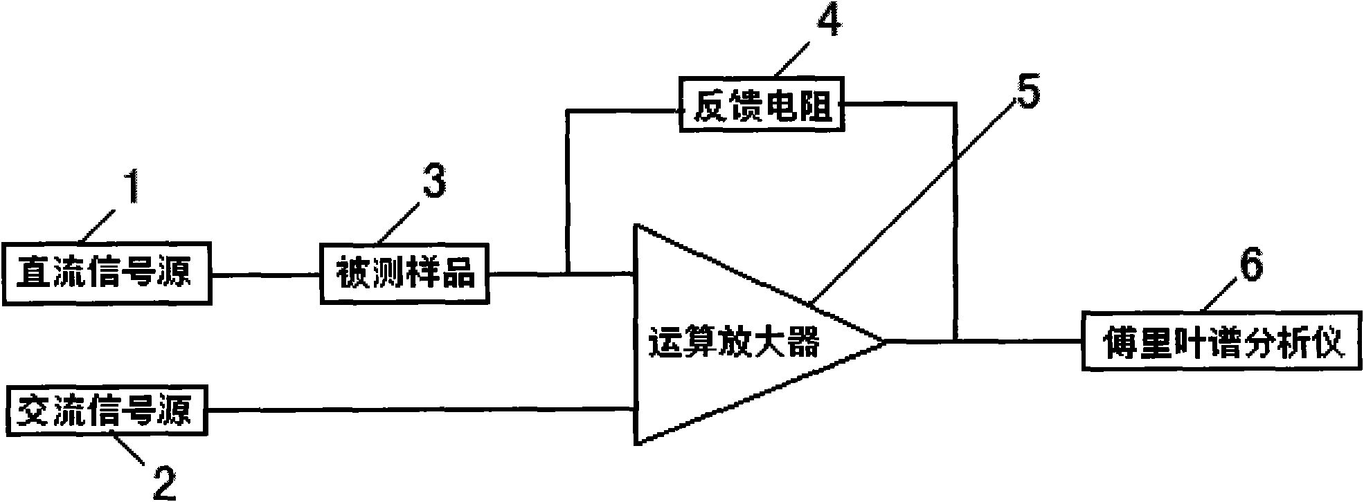
[0025] Such as figure 1 As shown, the present invention is realized in this way, a kind of conductance and differential conductance synchronous measuring device comprises DC signal source 1, AC signal source 2, operational amplifier 4, feedback resistance 5, Fourier spectrum analyzer 6, it is characterized in that The AC signal source 2 is connected to the positive input terminal of the operational amplifier 4, the DC signal source 1 is connected to the sample 3 to be tested and then connected to the negative input terminal of the operational amplifier 4, the output terminal of the operational amplifier 4 is connected to the Fourier spectrum analyzer 6, and the negative input of the operational amplifier 4 A feedback resistor 5 is connected between the terminal and the Fourier spectrum analyzer 6 .

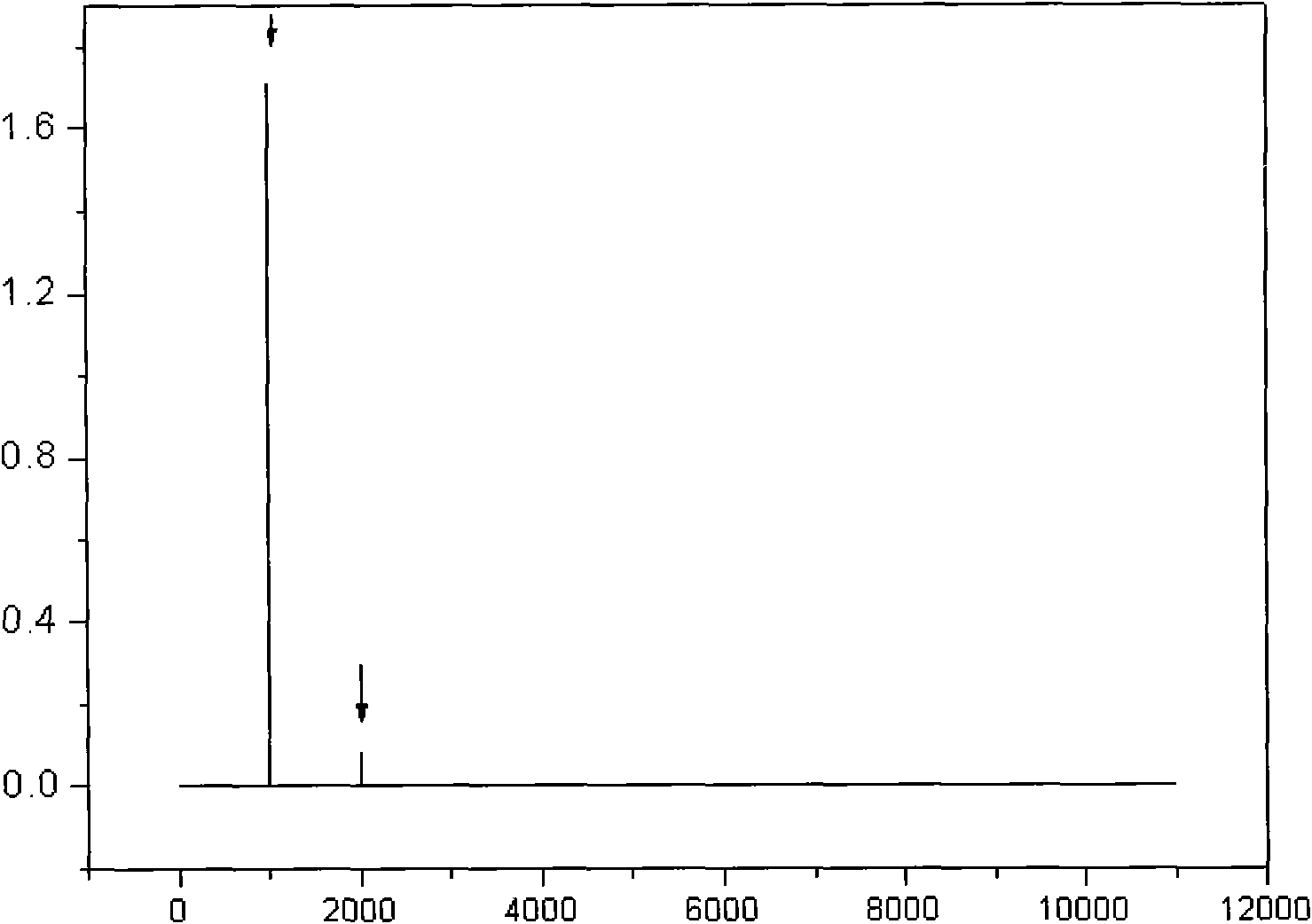
[0026] Such as figure 2 As shown, the abscissa in the figure is the Fourier transform frequency, and the ordinate is the Fourier transform coefficient. We use this system to mea...


PUM


Abstract

A conductance and differential conductance synchronous measuring device comprises a DC signal source, an AC signal source, an operational amplifier, a feedback resistor and a Fourier spectrum analyzer, and is characterized in that the AC signal source is connected with the positive input end of the operational amplifier; the DC signal source is connected with a tested sample and then connected with the negative input end of the operational amplifier, the output end of the operational amplifier is connected with the Fourier spectrum analyzer; and the feedback resistor is connected between the negative input end of the operational amplifier and the Fourier spectrum analyzer. The invention has the following advantages: firstly, the interaction of AC / DC voltage signals can be prevented so as to improve the signal-to-noise ratio; secondly, the accuracy of measurement results is monitored; thirdly, a measuring circuit can synchronously measure conductance and differential conductance to realize ultra-high resolution measurement on sample conductance variation; and fourthly, the measuring circuit is simple and easy in implementation.

Description

technical field [0001] The invention relates to a synchronous measuring device and method, in particular to a synchronous measuring device and method for conductance and differential conductance. Background technique [0002] Conductivity testing technology is widely used in electronics, chemical industry, biology, medicine, environmental protection and other fields, such as measurement of electronic tunneling characteristics, liquid composition analysis, biological tissue detection, etc. The usual method is to measure the current-voltage relationship, and then perform numerical differentiation to obtain the conductance [(Thomas D.E., et al.. Rev Sci Ins, 1963.34 (8): 920), (William R, et al.. Rev Sci Ins, 1964.35( 12): 1704)], but because the accuracy of the voltage source meter is low, and the jump point will occur when the range is changed, which seriously affects the conductance measurement result. There is also the use of lock-in amplification technology [Huang Zhiyao,...

Claims


Application Information

Patent Timeline
IPC IPC(8): G01R27/04G01R27/06
Inventor 肖文波何兴道
Owner NANCHANG HANGKONG UNIVERSITY
Why Eureka
Try Eureka