NANDFLASH management method based on FAT file system
A management method and file system technology, applied in the field of NANDFLASH management based on the FAT file system, can solve the problems of consuming CPU resources, slowing down the system speed, and increasing the storage space, so as to improve reliability and stability, shorten the development cycle, The effect of simple method
- Summary
- Abstract
- Description
- Claims
- Application Information
AI Technical Summary
Problems solved by technology
Method used
Image

Examples
Embodiment 1
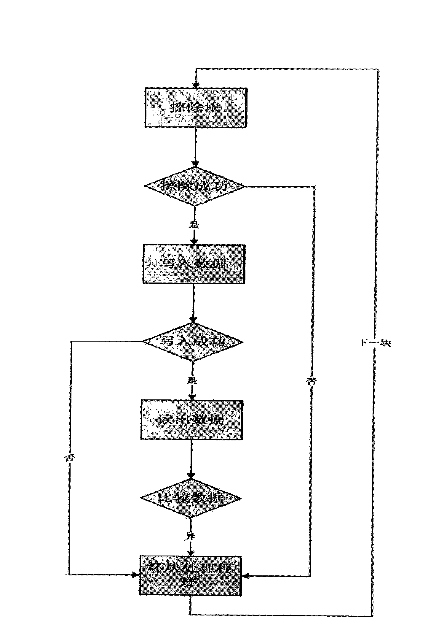
[0027] Such as figure 1 Shown, a kind of NANDFLASH management method based on FAT file system, at first is to detect each block in NANDFLASH, find out bad block, then handle bad block, convert the physical address of bad block into cluster number, finally in In the FAT table, the cluster number of the bad block is marked; the value of the mark must be greater than the maximum cluster number in the FAT table, in order to make the mark value not repeat with the effective cluster number, and in this way, it will never be written into the file It will not be written to this cluster.
[0028] The conversion of the physical address of the bad block into the cluster number is carried out by the bad block processing program, and the converted code is:
[0029] for(i=0; i
[0030] {
[0031] BadClusNum[i]=BadBlkNum*ClusPerBlk+2;
[0032]}
[0033] Among them, ClusPerBlk represents the number of clusters per block; BadClusNum represents the cluster number correspo...
Embodiment 2
[0042]When NAND FLASH is formatted, the computer will calculate the relevant information according to the capacity of FLASH and put it into DBR. FAT divides the FLASH space according to a certain number of sectors, each sector is 512Bytes, and multiple sectors constitute a " cluster". The following structure is the detailed information in DBR:
[0043] #define UINT8 unsigned char
[0044] #define UINT16 unsigned int
[0045] #define UINT32 unsigned long
[0046] typedef struct
[0047] {
[0048] UINT8 jmpBoot[3]; / *jump instruction * /
[0049] UINT8 OEMName[8]; / *Manufacturer name * /
[0050] UINT16 BytsPerSec; / *Bytes per sector * /
[0051] UINT8 SecPerClus; / *Number of sectors per cluster * /
[0052] UINT16 RsvdSecCnt; / * Number of reserved sectors * /
[0053] UINT8 NumFATs; / *Number of FAT tables * /
[0054] UINT16 RootEntCnt; / *The maximum number of files in the root directory, which is 0 in FAT32 * /
[0055] UINT16 TotSec16; / * Total num...
PUM
 Abstract
Description
Claims
Application Information
PatSnap Eureka turns technology decisions into work you can execute. Powered by our Innovation Knowledge Graph, it runs expert workflows across engineering, life sciences, materials and intellectual property. Get your review-ready output in minutes.


