Gas-oil-water separation system

A separation system, gas-oil-water technology, applied in separation methods, liquid separation, dispersed particle separation, etc., can solve the problem that oil and water cannot be separated

Active Publication Date: 2010-03-17
CHINA NAT OFFSHORE OIL CORP +2
View PDF1 Cites 3 Cited by
  • Summary
  • Abstract
  • Description
  • Claims
  • Application Information

AI Technical Summary

Problems solved by technology

In actual application, the liquid is a mixture of oil and water. In this way, although the gas in the crude oil

Method used


Image

  • Gas-oil-water separation system
  • Gas-oil-water separation system
  • Gas-oil-water separation system

Examples


Embodiment Construction

[0041] The present invention will be further described in detail below in conjunction with the accompanying drawings and embodiments.

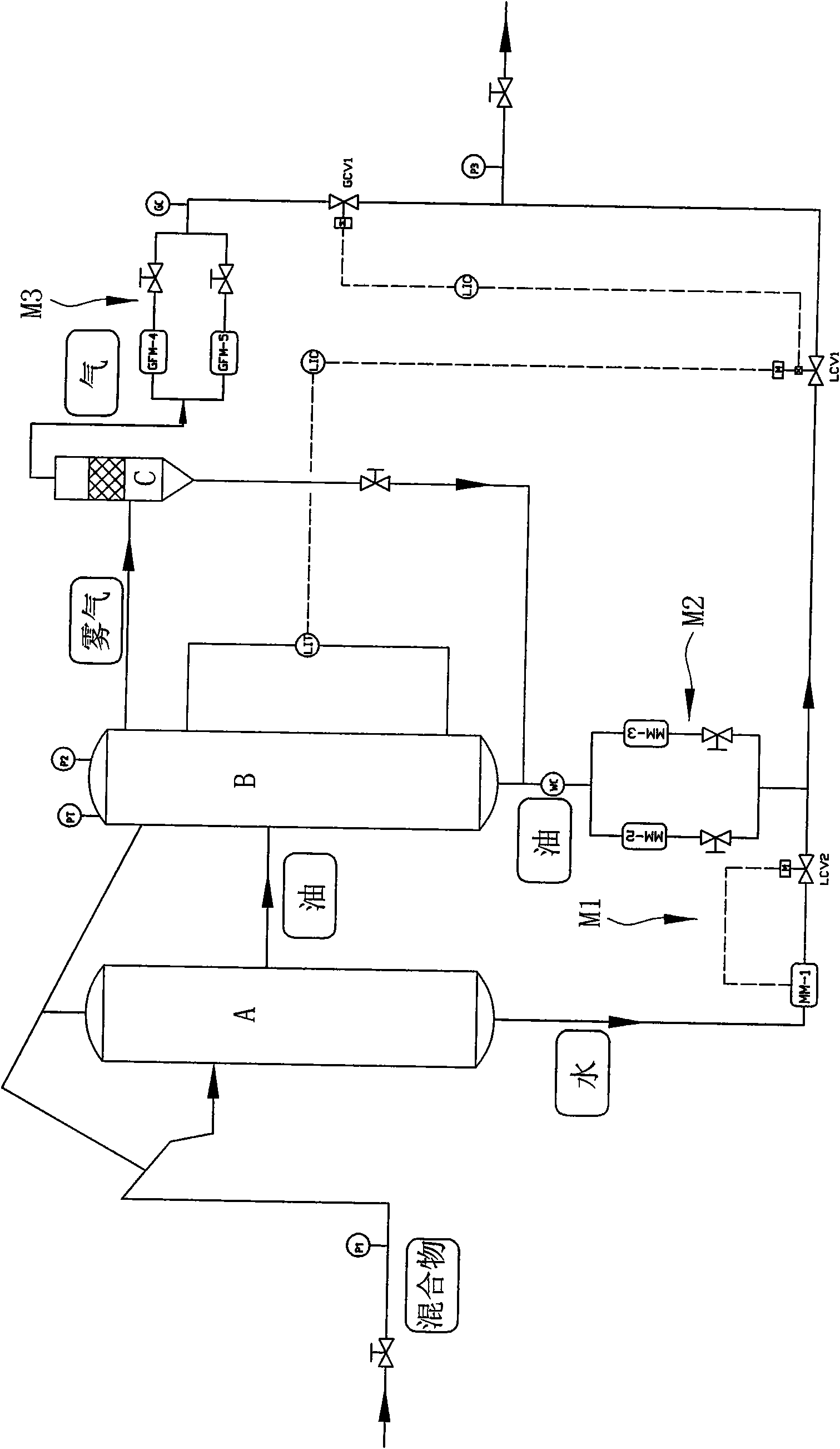
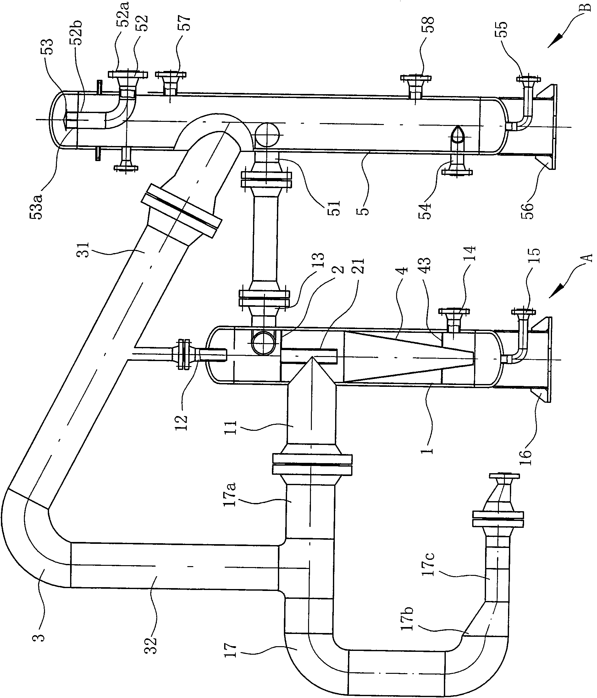
[0042] Such as Figure 1 to Figure 6 As shown, the gas-oil-water separation system includes a cyclone-type gas-oil-water separator A, a cyclone-type gas-oil separator B and a mist catcher C.

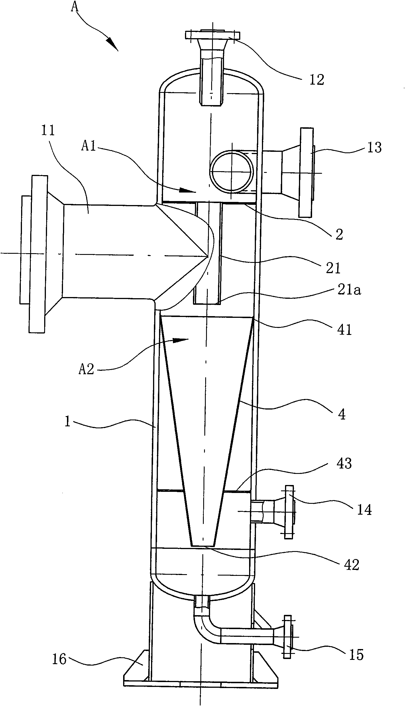
[0043] Among them, such as figure 2 , image 3 As shown, the cyclone-type gas-oil-water separator A includes a first columnar body 1, and the wall of the first columnar body 1 is sequentially provided with holes communicating with the interior of the first columnar body 1 from the top to the bottom. The first air outlet pipe 12, the first oil outlet pipe 13, the first input pipe 11, and the water outlet pipe 14, the first input pipe 11 is tangent to the cylinder wall of the first cylindrical cylinder body 1, and is on the wall of the first cylindrical cylinder body 1 There is a sewage outlet 15 at the bottom, and a first skirt support 16 is also prov...


PUM


Abstract

The invention discloses an gas-oil-water separation system comprising a spiral-flow type gas-oil-water separator (A), a spiral-flow type gas-oil-water separator (B) and a mist catcher (C), wherein thespiral-flow type gas-oil-water separator (A) comprises a first cylindrical barrel (1) which is provided with a first gas outlet pipe (12), a first oil outlet pipe (13), a first input pipe (11) and awater outlet pipe (14); the spiral-flow type gas-oil-water separator (B) comprises a second cylindrical barrel (5); the first gas outlet pipe (12) is communicated with a second input pipe (3) of the second cylindrical barrel (5); the first oil outlet pipe (13) is communicated with an oil phase material input pipe (51) of the second cylindrical barrel (5); and the mist catcher (C) comprises a tank(6) and a liquid drop collecting layer (7); and a second gas outlet pipe (52) is communicated with a third input pipe (62) of the tank (6). The gas-oil-water separation system not only is applicable to multi-phase separation of oil wells and moist wells with different gas-oil ratio ratios, adapts to 0-100 percent of containing water ratio change, and has wide application environment, but also cancarry out check to the accuracy degree of the existing multi-phase flow meter or gas-oil-water separation equipment.

Description

technical field [0001] The invention belongs to the technical field of fluid separation, and in particular refers to a gas-oil-water separation system that can finally realize the three-phase separation of gas, oil and water. The multi-phase separation of oil wells and wet gas wells with oil ratio can also be used to check the accuracy of current multi-phase flowmeters or gas-oil-water separation equipment. Background technique [0002] At present, in the oil field surface gathering and transportation system, various three-phase separators are mainly used to separate the natural gas, oil and water in the gas-oil-water mixture produced by the oil well, and then realize liquid metering or production metering. Traditional three-phase separators only rely on gravity to naturally separate gas, oil, and water. The oil content in the final output water is still high, and the separation effect is not ideal, and it is not suitable for use with different gas, oil, and water content ra...

Claims


Application Information

Patent Timeline
IPC IPC(8): B01D17/038B01D19/00B01D45/12
Inventor 王守波仇晨郑永建谢玉洪柯吕雄俞进唐广荣徐文江李耀林秦立峰
Owner CHINA NAT OFFSHORE OIL CORP
Why Eureka
Try Eureka