Washing dryer

A technology for washing and drying machines and washing tanks, which is applied to washing devices, household clothes dryers, washing machines with containers, etc., and can solve problems such as abnormal discharges

Active Publication Date: 2010-03-17
PANASONIC CORP
View PDF3 Cites 9 Cited by
  • Summary
  • Abstract
  • Description
  • Claims
  • Application Information

AI Technical Summary

Problems solved by technology

[0012] In addition, since the electrostatic atomization device applies a voltage between the electrodes to generate charged fine particle water, abnormal discharge may occur in a high-humidity environment.

Method used


Image

  • Washing dryer
  • Washing dryer
  • Washing dryer

Examples


Embodiment approach 1

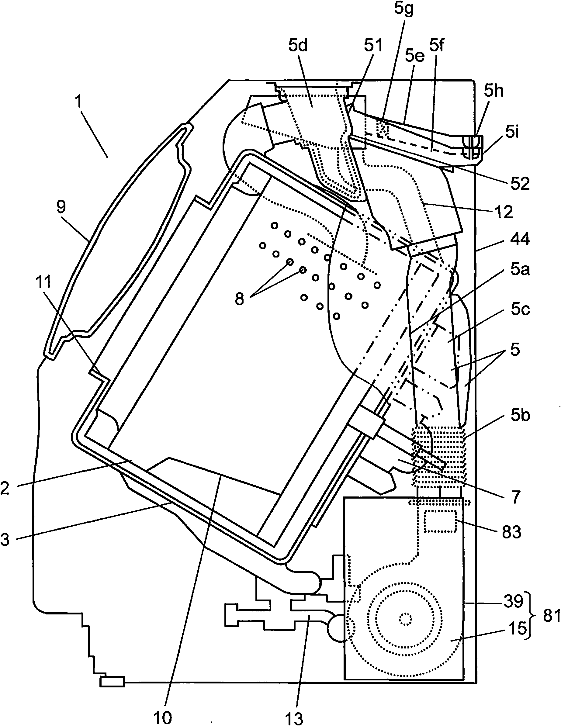
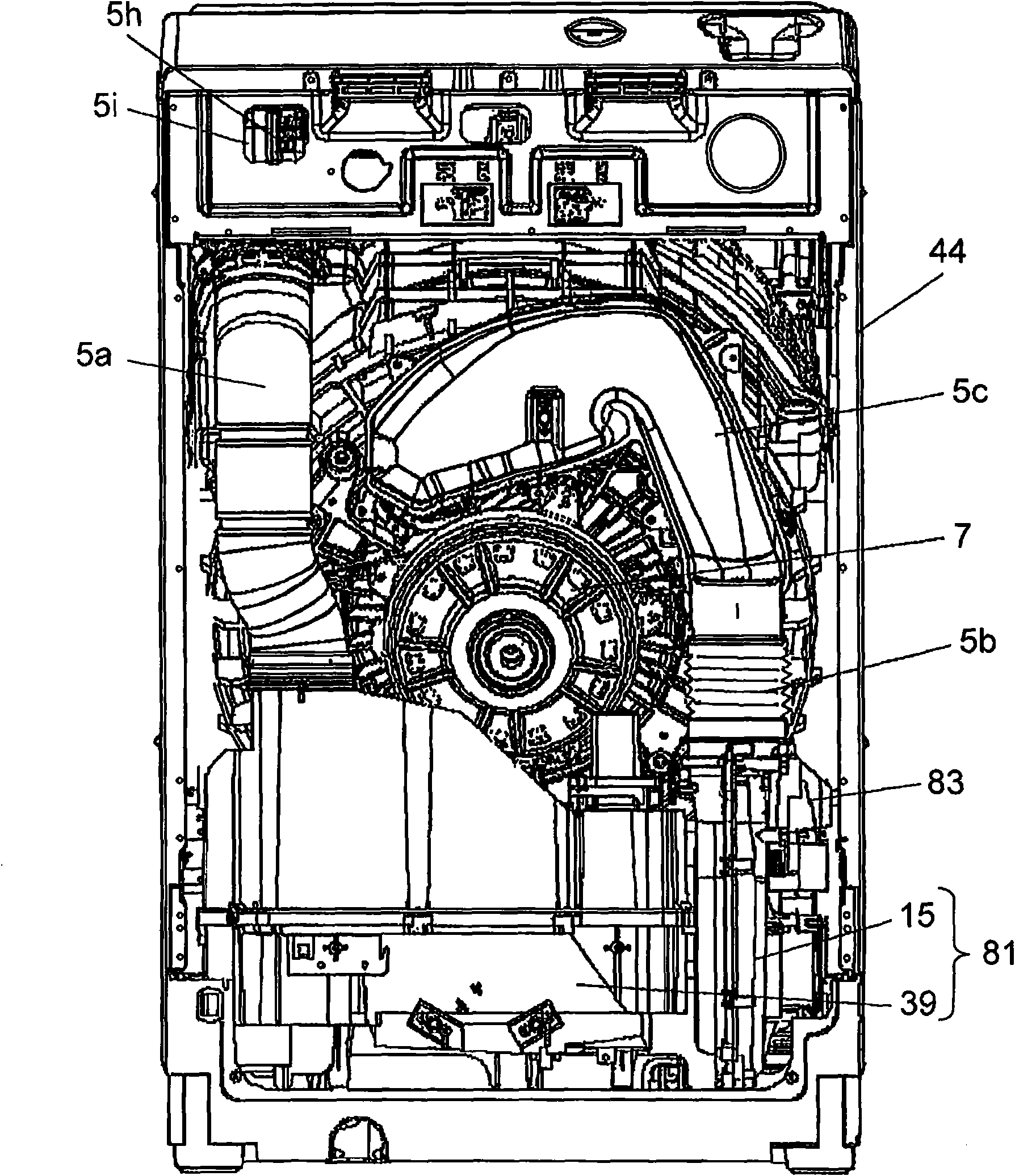
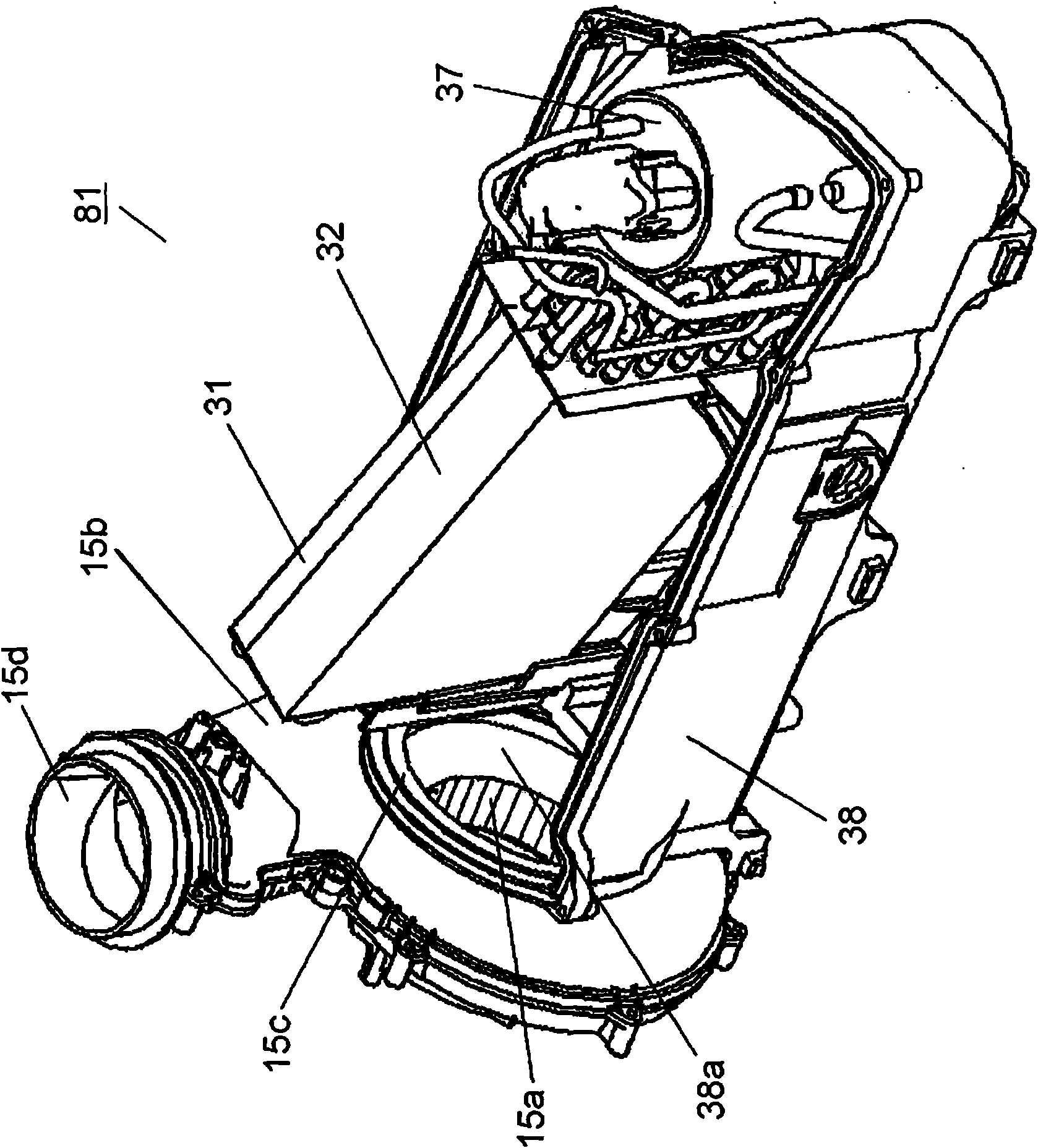
[0028] figure 1 It is a sectional view showing the structure of main parts of the washing and drying machine according to Embodiment 1 of the present invention, figure 2 is an internal rear view showing the circulating air supply path and the back of the outer tank of the washing and drying machine, image 3 It is a perspective view which shows the inside of the heat pump ventilation unit of this washing and drying machine.

[0029] Such as Figure 1 ~ Figure 3 As shown, in the washing and drying machine 1 , the washing tank 2 for accommodating laundry can be rotatably arranged in the outer tank 3 in such a way that its rotation axis direction is horizontal or inclined downward relative to the horizontal direction toward the rear. The washing and drying machine 1 has a drying process in addition to the processes of washing, rinsing, and dehydration.

[0030] The drying process is a process of repeating the following work to dry the laundry. The above work refers to: using ...

Embodiment approach 2

[0062] Figure 8 It is a longitudinal sectional view of the washing and drying machine according to Embodiment 2 of the present invention. In Embodiment 2 of the present invention, description of the same configuration, operation, and effect as Embodiment 1 will be omitted, and only differences will be described.

[0063] Such as Figure 8 As shown, the rotary drum 121 as the washing tank of the drum type washing and drying machine is formed in a bottomed cylindrical shape, and a plurality of through holes 122 are provided on the entire surface of the outer periphery thereof, and the rotary drum 121 is freely rotatably disposed on the Inside the bucket tank 123 as the outer tank. The rotating shaft 124 is provided at the center of rotation of the rotating drum 121 obliquely with respect to the horizontal direction, and the axial center direction of the rotating drum 121 is inclined downward from the front side toward the rear side. The rotating shaft 124 is connected with a...


PUM


Abstract

The present invention provides a washing dryer which comprises the following components: a washing tank; a outer tank; a housing which elastically supports the outer tank; a water supply device whichsupplies washing water to the outer tank; a heating device which heats the air in the outer tank; a circulating air feeding path for circulating the air in the outer tank through the heating device; an air feeding device which pressurizes and conveys the air in the circulating air feeding path for circulating; an electrostatic atomization generator which is provided in the circulating air feedingpath and supplies the particles through electrostatic atomization into the outer tank, wherein the circulating air feeding path is provided with an outer air entering part which causes the outer air to enter and a circulating air discharging part that discharges the air in the circulating air feeding path. The outer air entering part is composed of a first opening, an outer air guiding channel connected with the first opening, and an open and close valve. The circulating air discharging part is composed of a second opening and a circulating air discharging channel connected with the second opening.

Description

technical field [0001] The present invention relates to a washing and drying machine. Background technique [0002] In recent years, attention has been paid to the hygienic environment of the living space, and many hygienic products for achieving sterilization, deodorization, etc. have been distributed in the market. In laundry products, washing and drying machines having a function of sterilizing and deodorizing clothes, cloth products, leather products, toys, small items, etc. have also started to be sold. [0003] Generally, these washing and drying machines are provided with a dedicated program for putting objects into the washing tub and operating them for several tens of minutes. Regarding the specific means of sterilization and deodorization, for example, there are many methods such as heating in the tank, using ozone, and using chemicals, but basically heating is performed. [0004] In addition, the inside of the tank of the washing machine is worrying as a place w...

Claims


Application Information

Patent Timeline
Patent Type & Authority Applications(China)
IPC IPC(8): D06F25/00D06F33/00D06F58/20D06F58/28A61L9/14A61L2/02
Inventor 朝见直皿田洁辻川祐荣柳田国男
Owner PANASONIC CORP
Why Eureka
Try Eureka