Swinging-bucket type rotor pump

A rotor and casing technology, applied in the field of positive displacement fluid pumps, can solve the problems of short life, wear, and inability to form a high lift, and achieve the effect of improving the rotational speed and structural strength, and improving the lift and flow.

Inactive Publication Date: 2010-03-17
丑毅 +1
View PDF5 Cites 3 Cited by
  • Summary
  • Abstract
  • Description
  • Claims
  • Application Information

AI Technical Summary

Problems solved by technology

In this way, when it is running at low speed, it cannot form a high head, and the application occasions are limited; when the speed is high, the centrifugal force of the sliding vane is very large, and the reaction force provided by the inner w

Method used


Image

  • Swinging-bucket type rotor pump
  • Swinging-bucket type rotor pump
  • Swinging-bucket type rotor pump

Examples


Embodiment Construction

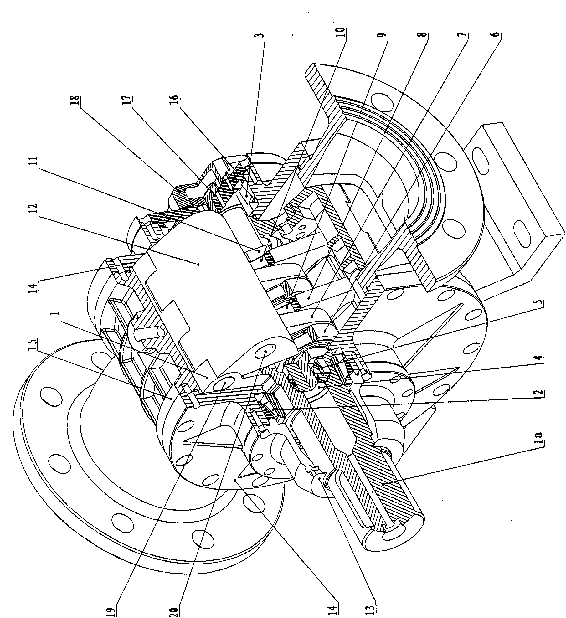
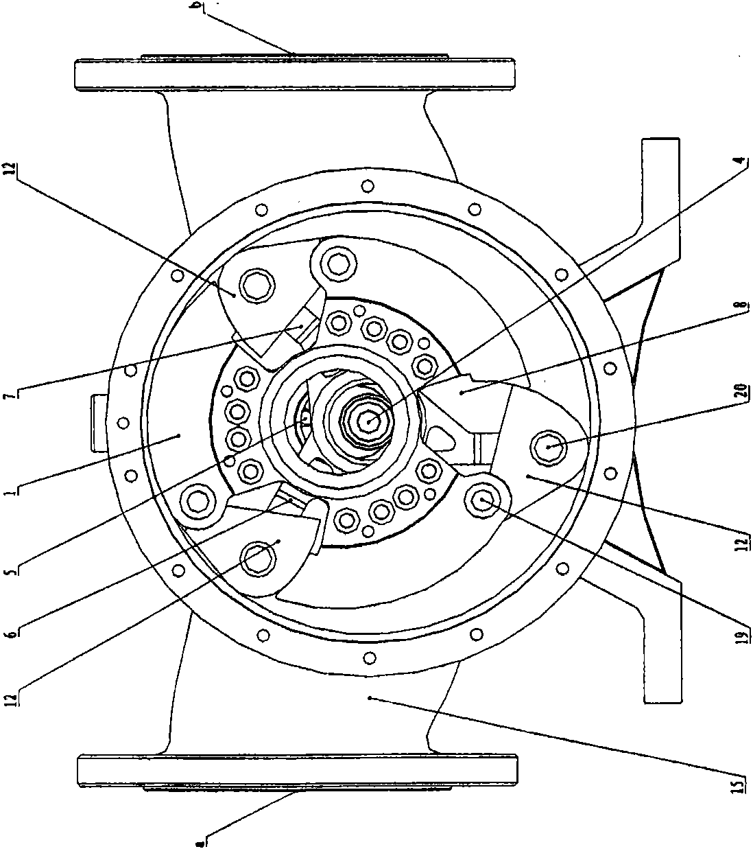
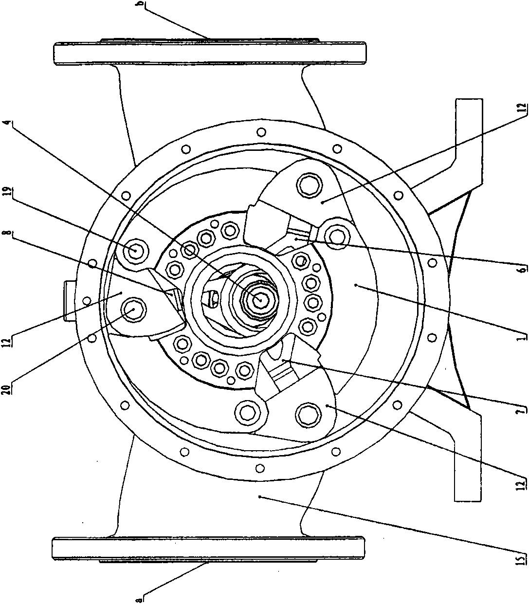
[0019] figure 1 Shown in is an exemplary embodiment of an oscillating bucket rotor pump according to the invention, which has a cylindrical housing 15 with a chamber for receiving the rotor 1 . The front end covers 13 and 14 and the rear end covers 16 and 18 are mounted on the front and rear sides of the casing 15 respectively in the axial direction, and are fastened into one body with bolts and positioned by pins.

[0020] External devices of the rotor pump, such as motors, input devices (such as shaft couplings), inlet and outlet pipes, and equipment with the rotor pump, are well known to those skilled in the art, so descriptions thereof are omitted here.

[0021] continue to see figure 1 , the cylindrical rotor 1 is eccentrically arranged in the chamber of the cylindrical housing 15, and the rotor 1 is not cut from the inner wall of the housing delimiting the chamber. One end 1 a of the central shaft of the rotor 1 protrudes through front end covers 13 , 14 to receive pow...


PUM


Abstract

The invention provides a swinging-bucket type rotor pump. The swinging-bucket type rotor pump comprises a cylinder-shaped shell, a rotor, a crankshaft, a plurality of support arms and a plurality of swinging buckets, wherein the rotor is eccentrically positioned relatively to the axis of the cylinder-shaped shell and provided with a plurality of radial notches that divide the rotor into a plurality of parts, one end, which is arranged along the circumferential direction, of each part is a connecting end, and the other end is provided with a circular arc surface; the crankshaft comprises a first part and a second part, the first part is coaxial with the central shaft of the rotor and supported by the central shaft of the rotor, and the second part is coaxial with the cylinder-shaped shell;one end of the each support arm is pivotally connected with the second part fixing the crankshaft; and each swinging bucket is arranged on the notch of the corresponding rotor respectively, one end of the swinging bucket is pivotally connected with the connecting end of one part of the rotor, and the other end of the swinging bucket is pivotally connected with the other end of the corresponding support arm, the other end of the swinging bucket comprises two sections of circular arc surfaces which are mutually tangential, one section of circular arc surface is matched with the circular arc surface of the adjacent part, and the radius of the other section of circular arc surface is equal to the length difference of the internal diameter of the cylinder-shaped shell and the support arm.

Description

technical field [0001] The invention relates to a positive displacement fluid pump, especially a swinging bucket rotor pump, wherein the rotor is not in direct contact with the housing. Background technique [0002] Existing industrial pumps mainly include vane pumps and volumetric pumps. Vane pumps can be divided into centrifugal pumps, vortex pumps, mixed flow pumps, axial flow pumps, etc. Positive displacement pumps also include reciprocating and rotor types. The vane pump is characterized by a large flow rate and a relatively small head, and the positive displacement pump is characterized by a large head and a relatively small flow rate. However, it is still difficult to produce a pump with high lift and high flow rate with a relatively small volume. [0003] There is a kind of sliding vane pump in the rotor pump. The sliding vane of this type of pump is not fixed. When rotating, the power directly drives the rotor, and the rotor drives the sliding vane. contact to for...

Claims


Application Information

Patent Timeline
IPC IPC(8): F04C2/34F04C15/00
Inventor 丑毅
Owner 丑毅
Why Eureka
Try Eureka