Method for measuring flame propagation velocity of Bunsen burner during combustion process of gaseous fuel

A flame propagation speed and gas fuel technology, which is applied in the field of flame propagation speed measurement, can solve the problems of complex measurement process and low accuracy, and achieve the effects of simple measurement process, improved accuracy and error elimination.

Inactive Publication Date: 2010-03-17
HARBIN INST OF TECH
View PDF0 Cites 15 Cited by
  • Summary
  • Abstract
  • Description
  • Claims
  • Application Information

AI Technical Summary

Problems solved by technology

[0003] The present invention aims to solve the problems of low measurement accuracy and complicated measurement process of the existing gaseous fuel in the flame propagation process of the Bunsen burner, so as to provide the measurement of the flame propagation velocity of the gaseous fuel in the combustion process of the Bunsen burner method

Method used


Image

  • Method for measuring flame propagation velocity of Bunsen burner during combustion process of gaseous fuel
  • Method for measuring flame propagation velocity of Bunsen burner during combustion process of gaseous fuel
  • Method for measuring flame propagation velocity of Bunsen burner during combustion process of gaseous fuel

Examples


specific Embodiment approach 1

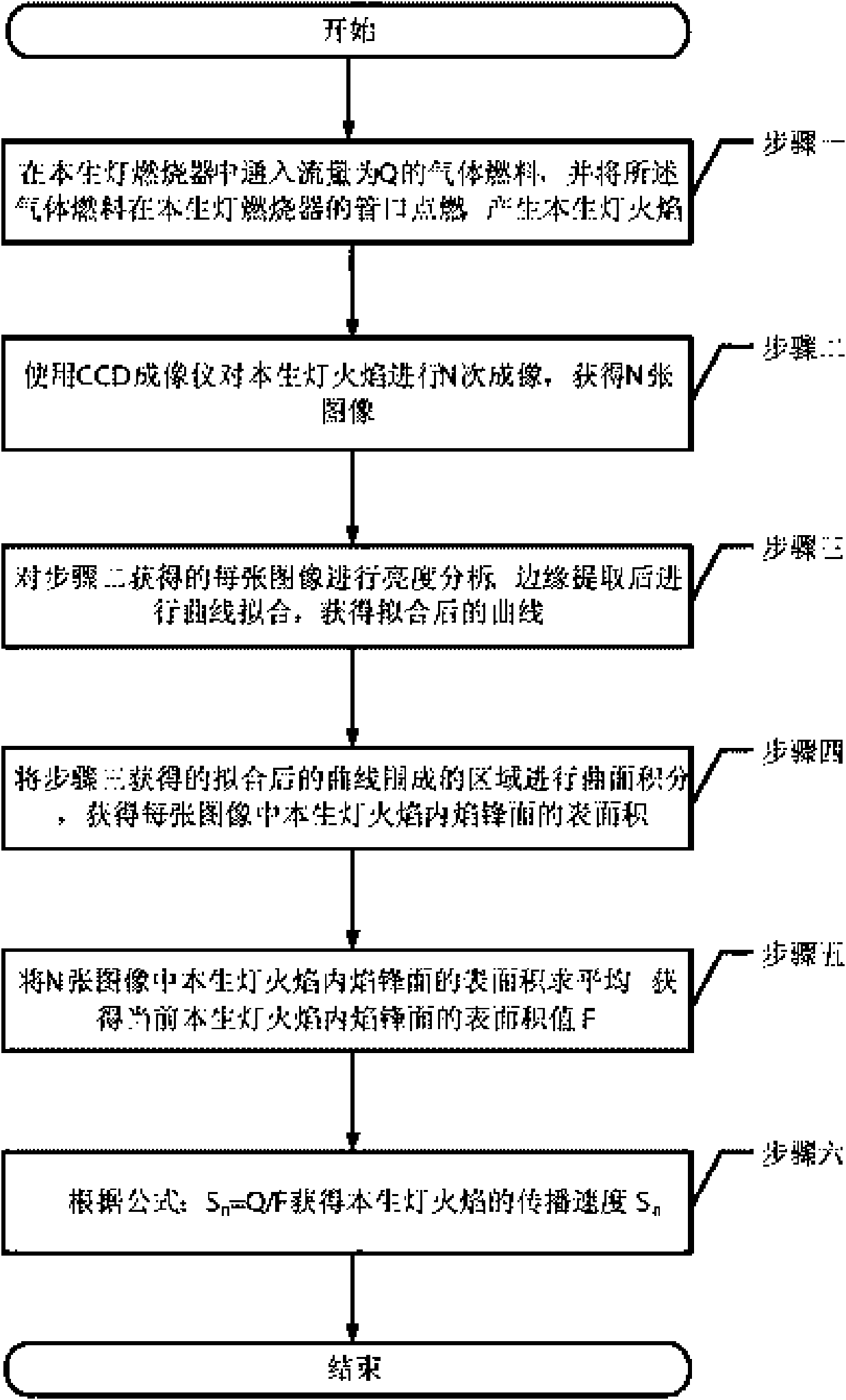
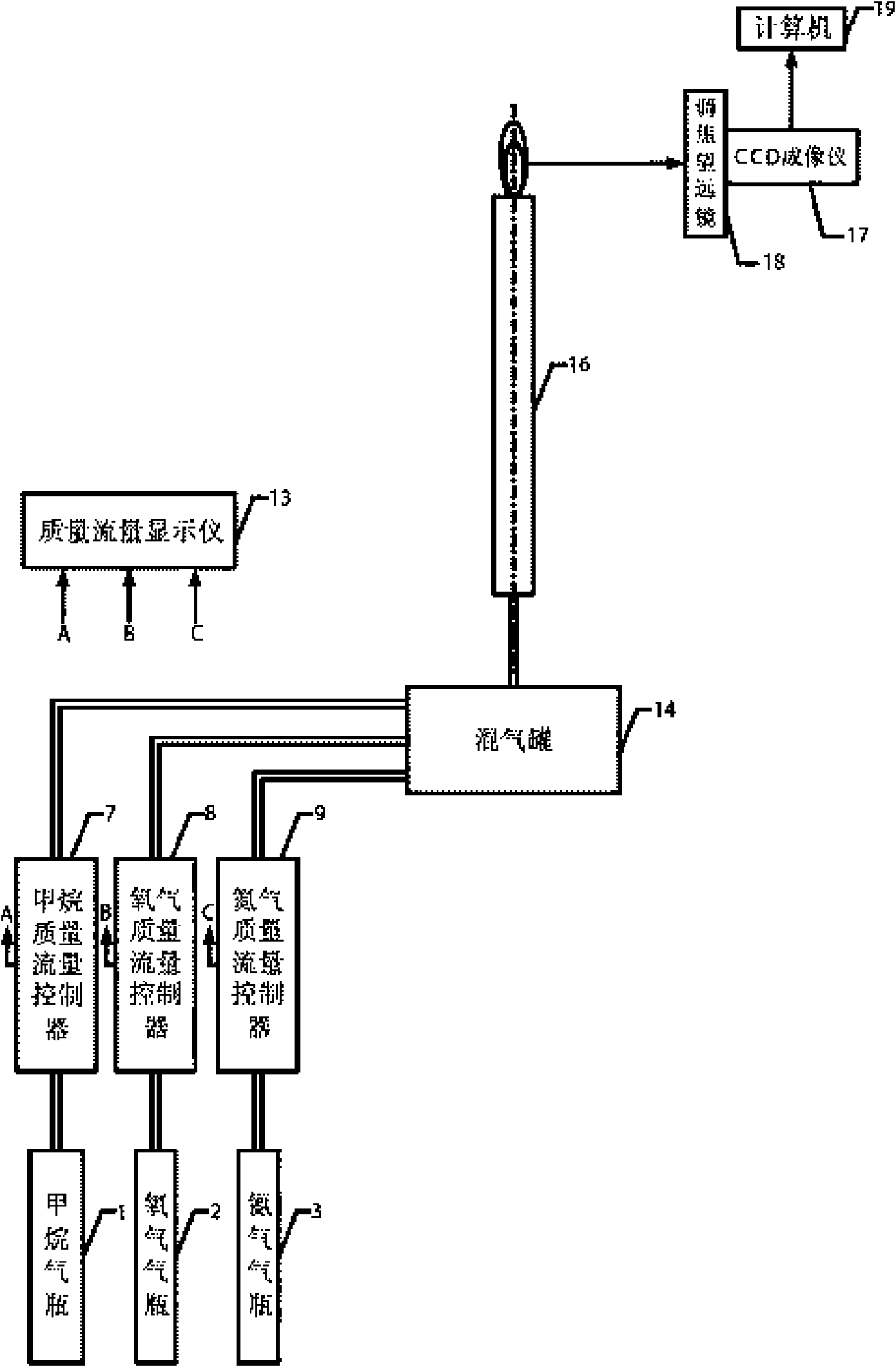
[0016] Specific implementation mode 1. Combination figure 1 Illustrate this specific embodiment, the measurement method of flame propagation velocity of gaseous fuel in the combustion process of Bunsen burner, it is realized by the following steps:

[0017] Step 1, in the Bunsen burner burner 16, feed the gas fuel with a flow rate of Q, and ignite the gas fuel at the mouth of the Bunsen burner burner 16 to generate a Bunsen burner flame;

[0018] Step 2, adjust the focal length between the Bunsen burner flame and the CCD imager 17 through the focusing telescope 18 arranged at the optical input end of the CCD imager 17, and then use the CCD imager 17 to perform N times of imaging on the Bunsen burner flame to obtain N sheets image;

[0019] Step 3, perform brightness analysis on each image obtained in step 2, and perform curve fitting after edge extraction to obtain a fitted curve;

[0020] Step 4, performing surface integration on the area enclosed by the fitted curve obtain...

specific Embodiment approach 2

[0026] Embodiment 2. The difference between this embodiment and the method for measuring the flame propagation velocity of the gaseous fuel in the combustion process of the Bunsen burner described in Embodiment 1 is that the flame propagation of the gaseous fuel in the flame process of the Bunsen burner The speed measurement method is characterized in that the gas fuel is a mixed fuel of methane, oxygen and nitrogen.

specific Embodiment approach 3

[0027] Specific embodiment three, the difference between this specific embodiment and the method for measuring the flame propagation velocity of the gaseous fuel described in specific embodiment two in the combustion process of the Bunsen burner is that the volume ratio of the methane is 6% to 50%, oxygen The volume ratio of nitrogen is 13% to 70%, and the volume ratio of nitrogen is 10% to 80%.


PUM


Abstract

The invention relates to a method for measuring the flame propagation velocity of a Bunsen burner during the combustion process of gaseous fuel, relating to a method for measuring the flame propagation velocity. The method for measuring the flame propagation velocity of a Bunsen burner during the combustion process of gaseous fuel is realized by the following steps of: igniting gaseous fuel with aflow rate Q in the Bunsen burner to generate flame of the Bunsen burner; performing N times of imaging on the flame of the Bunsen burner by a CCD imaging device to obtain N images; performing brightness analysis and edge extraction on each image and then performing curve fitting; performing curve integration on the area surrounded by the fit curve to obtain the superficial areas of the inner flame frontal surfaces in the flame of the Bunsen burner in each image, averaging the superficial areas to obtain the current superficial area value of the inner flame frontal surface in the flame of theBunsen burner; and calculating the flame propagation velocity of the Bunsen burner according to the superficial area value of the inner flame frontal surface in the flame and the gas flow rate. The method for measuring flame propagation velocity of Bunsen burner during combustion process of gaseous fuel is suitably used for measuring the flame propagation velocity of the Bunsen burner during the combustion process of gaseous fuel.

Description

technical field [0001] The invention relates to a method for measuring flame propagation speed. Background technique [0002] Flame propagation velocity is the velocity at which a plane flame wave front moves through adjacent unburned gas in a direction perpendicular to its surface. Flame propagation velocity is a basic constant of combustible gas mixture, which not only has great practical significance in considering the stability of flame, but also has great theoretical value in studying the theory of flame propagation. However, the planar flame wavefront can only be obtained under very special conditions. In almost all practical cases, the flame wavefront is either distorted or not perpendicular to the airflow velocity, so it is difficult to measure it directly. Commonly used flame propagation velocity calculation methods include the Gooy flame area method, the Bunsen burner flame method, the nozzle method, and the particle tracer method. And these methods all have some...

Claims


Application Information

Patent Timeline
Patent Type & Authority Applications(China)
IPC IPC(8): G01P3/38
Inventor 孙锐于欣彭江波杨鹏陈德应刘辉杨晓川伊亚超
Owner HARBIN INST OF TECH
Why Eureka
Try Eureka