Unlock instant, AI-driven research and patent intelligence for your innovation.

Angular position driving device

A driving device and angular position technology, applied in mechanical control devices, position/direction control, non-electric variable control, etc., can solve the problems of increased production cost and processing difficulty of worm gears, and can not meet the sun tracking angle range, etc., to achieve a simple structure , good stability and convenient processing of parts

Inactive Publication Date: 2010-03-17
容云
View PDF0 Cites 3 Cited by
  • Summary
  • Abstract
  • Description
  • Claims
  • Application Information

AI Technical Summary

Problems solved by technology

[0004] The angular position driving device of the above-mentioned worm wheel and worm structure is not suitable for solar systems with large-scale solar panels (large-scale solar panels can reduce the cost of solar systems, and are used more in solar systems), mainly because of the large size The solar panel needs the angular position driving device to have a larger load capacity. In order to carry a larger weight, a bearing with a larger diameter is required. If the angular position driving device with the above-mentioned worm wheel and worm structure is used, the size of the worm wheel must be larger than Bearing size, large-scale worm gears and worms require large machine tools and supporting molds, which greatly increases the production cost and processing difficulty of worm gears. If a linear electric cylinder 104 is used to drive the solar panel frame 101 to rotate around the horizontal axis 103 To drive the moving frame 102 to rotate around the vertical axis, the range of rotation angle can only reach about 90 degrees, which cannot meet the nearly 200 degree range of rotation angle required for sun tracking.

Method used


Image

  • Angular position driving device
  • Angular position driving device
  • Angular position driving device

Examples


Embodiment 1

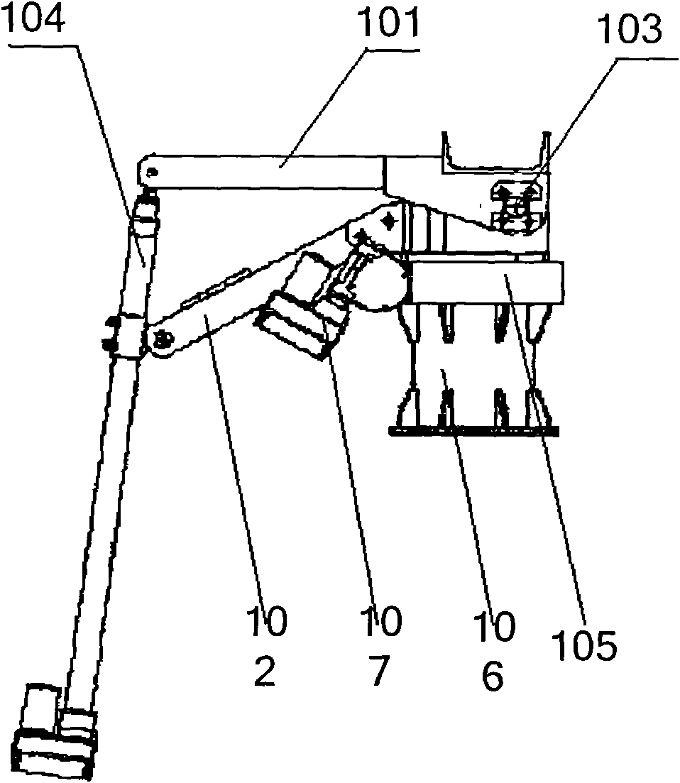
[0026] Embodiment 1 provides an angular position driving device, which can be used in various equipment that requires angular tracking, such as solar power generation equipment, etc. The angular position driving device includes: a fixed frame, a moving frame, at least one swing arm and at least two a linear electric cylinder;

[0027] Wherein, the fixed frame and the movable frame are connected coaxially, and the swing arm is connected with the coaxial place of the fixed frame and the movable frame, that is, the fixed frame, the movable frame and the swing arm form a coaxial movable connection; the fixed frame and the swing arm A linear electric cylinder is connected between them, and the linear electric cylinder forms a triangle structure with the fixed frame and the swing arm. The angle formed by the connection between the fixed frame and the swing arm relative to the cylinder is used as the apex angle of the triangle structure; another linear electric cylinder is connected ...

Embodiment 2

[0039] The second embodiment provides an angular position driving device. The structure of the angular position driving device is basically the same as that of the first embodiment above. The difference is that two or more swing arms are used in the angular position driving device, and At the same time increase the number of linear electric cylinders, these swing arms are coaxially connected with the fixed frame and the moving frame; A linear electric cylinder is connected between them, so that a triangle structure is formed between the linear electric cylinder and two adjacent swing arms. The linear electric cylinder is used as the bottom edge of the triangle structure, and the two swing arms are used as the other two sides. The opposite angle formed by the clamping of the two swing arms serves as the apex angle of the triangular structure. In the angular position drive device, in the triangular structure formed by the linear electric cylinder and two swing arms, the static a...


PUM


Abstract

The invention discloses an angular position driving device. The device comprises: a fixed frame, a movable frame, at least one swing arm and at least two linear electric cylinders, wherein the fixed frame and the movable frame are coaxially and movably connected; the swing arm is movably connected with the common axis of the fixed frame and the movable frame or either of the fixed frame and the movable frame; a linear electric cylinder is connected between the fixed frame and the swing arm, and the linear electric cylinder, the fixed frame and the swing arm form a triangular structure; anotherlinear electric cylinder is connected between the swing arm and the movable frame and also forms another triangular structure together with the movable frame and the swing arm; the triangular structure formed by the linear electric cylinder, the fixed frame and the swing arm adjoins the another triangular structure formed by another linear electric cylinder, the movable frame and the swing arm; and the included angle between the fixed frame and the movable frame equals to the sum of the vertex angles of the adjoined triangular structures. By adjusting the length of the linear electric cylinder to adjust the corresponding vertex angle, the device consequently realizes the adjustment of the angular position between the fixed frame and the movable frame and is characterized by simple structure, big changeable angles and great bearing capacity.

Description

technical field [0001] The invention relates to a mechanical driving device, in particular to an angular position driving device. Background technique [0002] In production and life, angular position driving devices are often used, such as sun trackers, etc.; existing sun trackers generally require two axes, and each axis needs to have a set of independent angular position driving devices, and one axis is vertical around the horizontal axis The rotation is generally realized by linear electric cylinder drive, and the horizontal rotation of one axis around the vertical axis is generally realized by worm gear and worm drive. figure 1 It is a side view of two shaft drive parts of a sun tracker using a worm gear and a worm drive in the prior art, including a worm gear 105, a worm 107, a fixed frame 106, a moving frame 102, a solar panel frame 101, a linear Parts such as electric cylinder 104, horizontal axis 103, from figure 1 It can be seen that in the sun tracker, the worm ...

Claims


Application Information

Patent Timeline
IPC IPC(8): G05D3/00G05G3/00
Inventor 容云
Owner 容云
Features
  • R&D
  • Intellectual Property
  • Life Sciences
  • Materials
  • Tech Scout
  • Unparalleled Data Quality
  • Higher Quality Content
  • 60% Fewer Hallucinations
Learn More