Apparatus for cleaning floor

An equipment and ground technology, applied in cleaning equipment, carpet cleaning, floor cleaning, etc., can solve problems such as reduced cleaning efficiency, and achieve the effect of high cleaning efficiency

Active Publication Date: 2010-03-17
NINGBO SAWADIKA ELECTRICAL APPLIANCE
View PDF4 Cites 20 Cited by
  • Summary
  • Abstract
  • Description
  • Claims
  • Application Information

AI Technical Summary

Problems solved by technology

However, given the fact that dirt is removed from the floor by friction between the floor

Method used


Image

  • Apparatus for cleaning floor
  • Apparatus for cleaning floor
  • Apparatus for cleaning floor

Examples


Embodiment Construction

[0024] The above and other objects, characteristics and other advantages of the present invention will be more clearly understood from the following detailed description in conjunction with the accompanying drawings. It should be noted that like reference numerals denote like parts throughout the drawings.

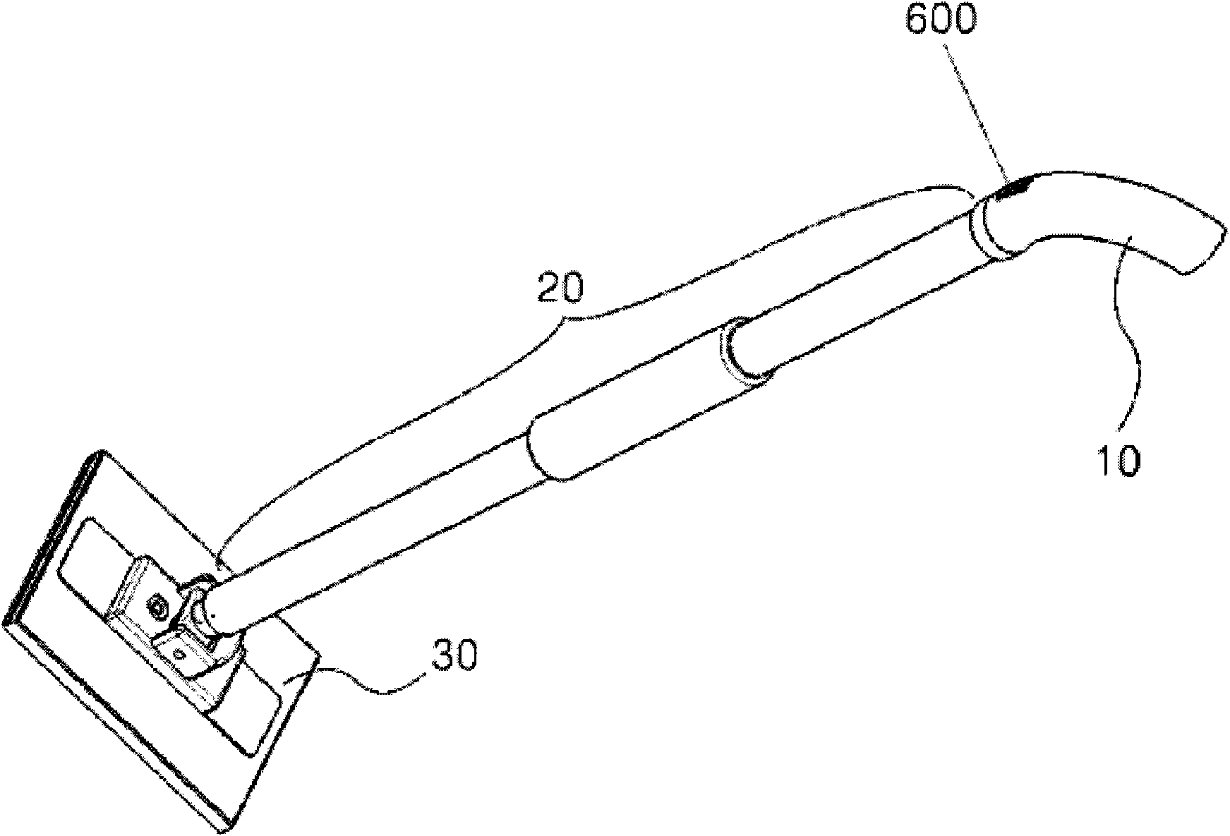
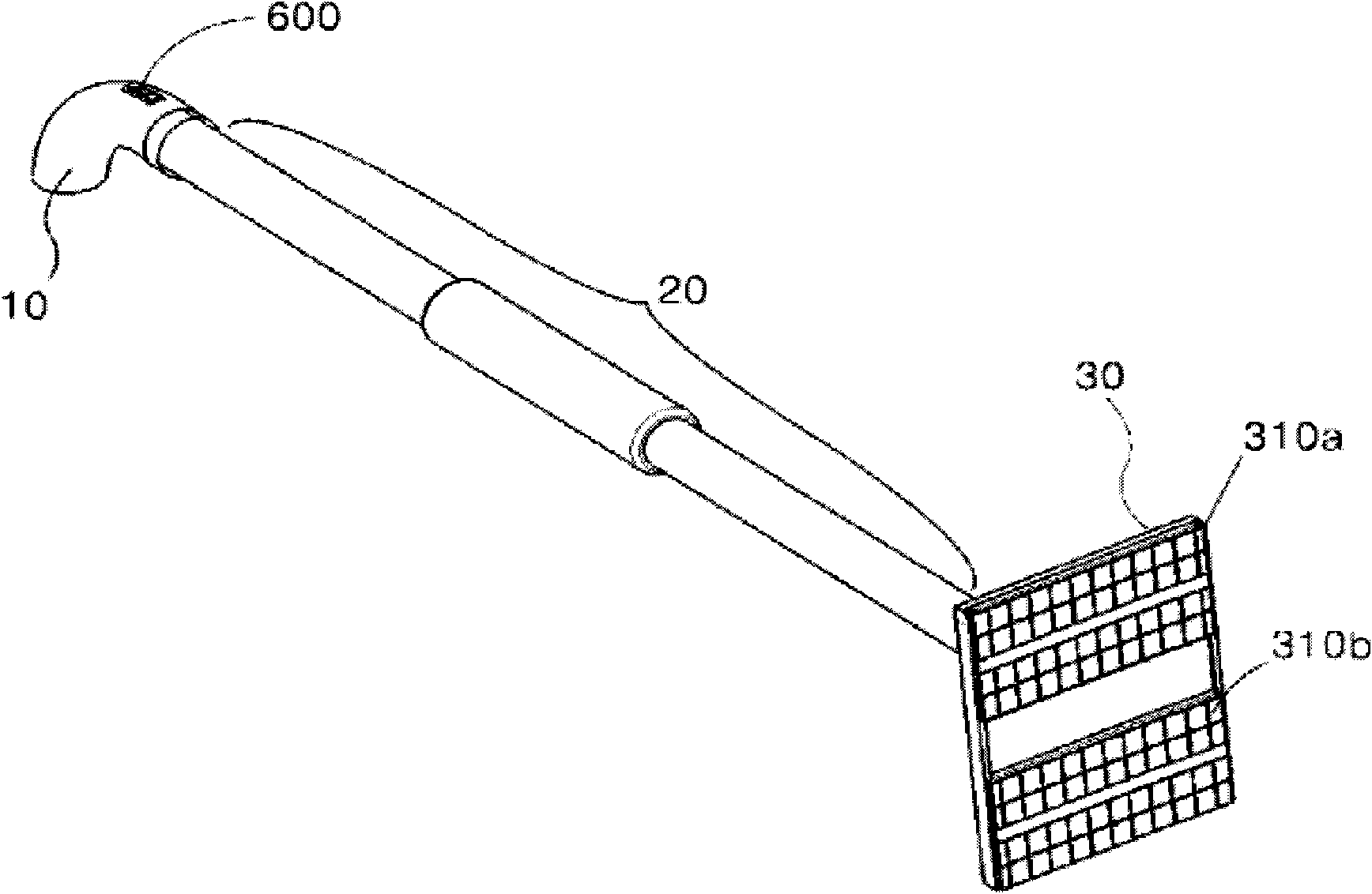
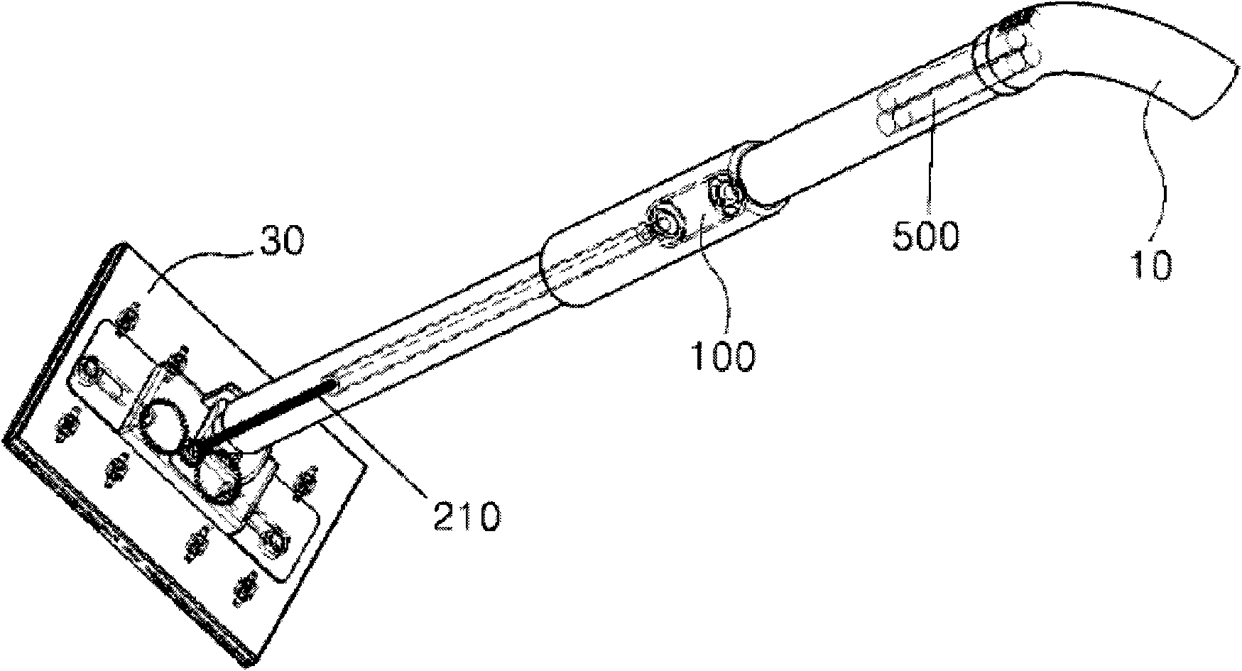
[0025] figure 1 is a schematic diagram showing the upper part of a device for cleaning floors according to the invention, figure 2 is a schematic diagram showing the bottom of the device for cleaning floors according to the present invention.

[0026] The device for cleaning the floor according to one embodiment of the present invention includes: a handle 10 having a switch 600 for operating the device; a support member 30 coupled to first and second movable members 310a and 310b; and a connection The tube 20 is located between the handle 10 and the support member 30 . The first and second movable members 310 a and 310 b are slidably coupled to the support member 30 su...


PUM


Abstract

Disclosed is an apparatus for cleaning floor capable of changing its moving direction without user's inconvenience caused by jolt or vibration generated when a floorcloth or brush automatically reciprocates in a straight line on the floor, the apparatus comprising a driving motor; a power-transmitting part for converting a rotary motion of the driving motor to a rectilinear reciprocating motion and transmitting a power of the rectilinear reciprocating motion; and a cleaning part rectilinearly reciprocating by the power supplied from the power-transmitting part, wherein the cleaning part includes first and second movable members arranged in parallel; wherein the first and second movable members respectively reciprocate along a same straight line in opposite directions to each other.

Description

technical field [0001] The present invention relates to an apparatus for cleaning floors, and more particularly, to an apparatus for cleaning floors capable of changing its direction of movement without causing inconvenience to the user, which is caused by Caused by swaying or vibration when the mop or brush automatically reciprocates in a straight line on the ground. Background technique [0002] In general, when cleaning the floor of a house or an office by using a wet mop, prior art cleaning methods using the wet mop mainly rely on user's physical labor. If the user tries to clean the floor with the prior art cleaning device using the wet mop, the user has to exert a lot of physical strength for reciprocating the prior art cleaning device using the wet mop. Therefore, if the floor is cleaned for a long time with the prior art cleaning equipment, the user will feel physically tired, and the cleaning efficiency will also become low. [0003] In particular, if the floor of...

Claims


Application Information

Patent Timeline
IPC IPC(8): A47L11/28
CPCA47L13/256A46B2200/3033A46B13/02A46B7/04
Inventor 金容旭
Owner NINGBO SAWADIKA ELECTRICAL APPLIANCE
Why Eureka
Try Eureka