Solar cell module

A solar cell and sheet technology, applied in photovoltaic modules, photovoltaic modules support structures, circuits, etc., can solve problems such as unsatisfactory decoration, and achieve the effects of excellent decoration, easy configuration, and improved productivity

Inactive Publication Date: 2010-03-17
MITSUBISHI ELECTRIC CORP
View PDF1 Cites 6 Cited by
  • Summary
  • Abstract
  • Description
  • Claims
  • Application Information

AI Technical Summary

Problems solved by technology

Therefore, the above-mentioned blank area where no solar battery cells are arranged has a zigzag shape with a different color tone from other parts, which is not ideal in terms of decoration.

Method used


Image

  • Solar cell module
  • Solar cell module
  • Solar cell module

Examples


Embodiment approach

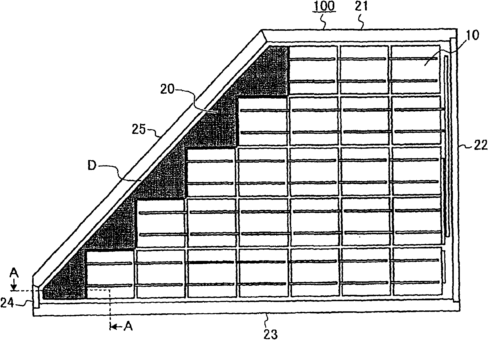
[0025] figure 1 is a front view of an embodiment of a solar cell module according to the present invention. figure 1 Here, the solar cell module 100 shown as an example has a substantially flat trapezoidal shape with one side being a hypotenuse. In addition, the solar battery cells 10 arranged on a plane correspond to the hypotenuse, while extending from figure 1 The lower row and the upper row gradually decrease in number, and the rows are arranged on the one hand. That is, 7 solar battery units 10 are arranged on the first bottom row, 6 solar battery units 10 are arranged on the second row, 5 solar battery units 10 are arranged on the third row, and 5 solar battery units 10 are arranged on the fourth row. Four solar battery cells 10, three solar battery cells 10 are arranged in the fifth row. In addition, since the solar battery cell 10 is formed in a substantially square flat plate shape, the edge of the solar battery cell group on the hypotenuse side is stepped. Theref...


PUM


Abstract

Solar cell module (100) comprising a laminate of multiple layers including cell arrangement layer (C) consisting of an arrangement of multiple solar cells (10) lined up. In order to attain enhancements of fanciness and productivity, thin plate (20) with the same color tone as that of the solar cells (10) is disposed in vacant region (D) of the cell arrangement layer (C) where the solar cells (10)are not laid. The thin plate (20) is disposed in the cell arrangement layer (C) in the same stage as that for laying of the solar cells (10) in the cell arrangement layer (C).

Description

technical field [0001] The present invention relates to a solar cell module formed by arranging a plurality of solar cell cells, and more particularly to a solar cell module having a hypotenuse shape. Background technique [0002] Most solar cell modules are installed on a large surface of a roof of a house. In addition, generally, a solar cell module is produced by aligning a plurality of substantially quadrangular or substantially rectangular solar cell cells in the vertical and horizontal directions in alignment with the module installation surface of the roof. Therefore, it is easy to arrange solar battery cells without gaps on a gable-shaped roof with a rectangular module installation surface (cut wife type), but on a veranda-shaped (kidori-type) roof with a trapezoidal or triangular module installation surface, The solar battery cells are arranged in steps on the hypotenuse of the module installation surface. Then, along with this, zigzag gaps (blank areas) arranged ...

Claims


Application Information

Patent Timeline
Patent Type & Authority Applications(China)
IPC IPC(8): H01L31/042
CPCY02E10/50H01L31/048Y02B10/12H01L31/0201H02S20/23Y02B10/10
Inventor 伊藤直树菅沼良之宫本慎介丸林典矢铃木一生
Owner MITSUBISHI ELECTRIC CORP
Why Eureka
Try Eureka