
Optical detecting system and method for classifying solar cells

A solar cell and optical detection technology is applied in the field of optical detection systems for classifying solar cells to achieve the effect of convenient production

Inactive Publication Date: 2010-03-24
CHROMA ELECTRONICS SHENZHEN
View PDF1 Cites 14 Cited by
  • Summary
  • Abstract
  • Description
  • Claims
  • Application Information

AI Technical Summary

Problems solved by technology

These requirements cannot be met by the current judgment logic of automatic optical inspection.

Method used


Image

  • Optical detecting system and method for classifying solar cells
  • Optical detecting system and method for classifying solar cells
  • Optical detecting system and method for classifying solar cells

Examples


Embodiment Construction

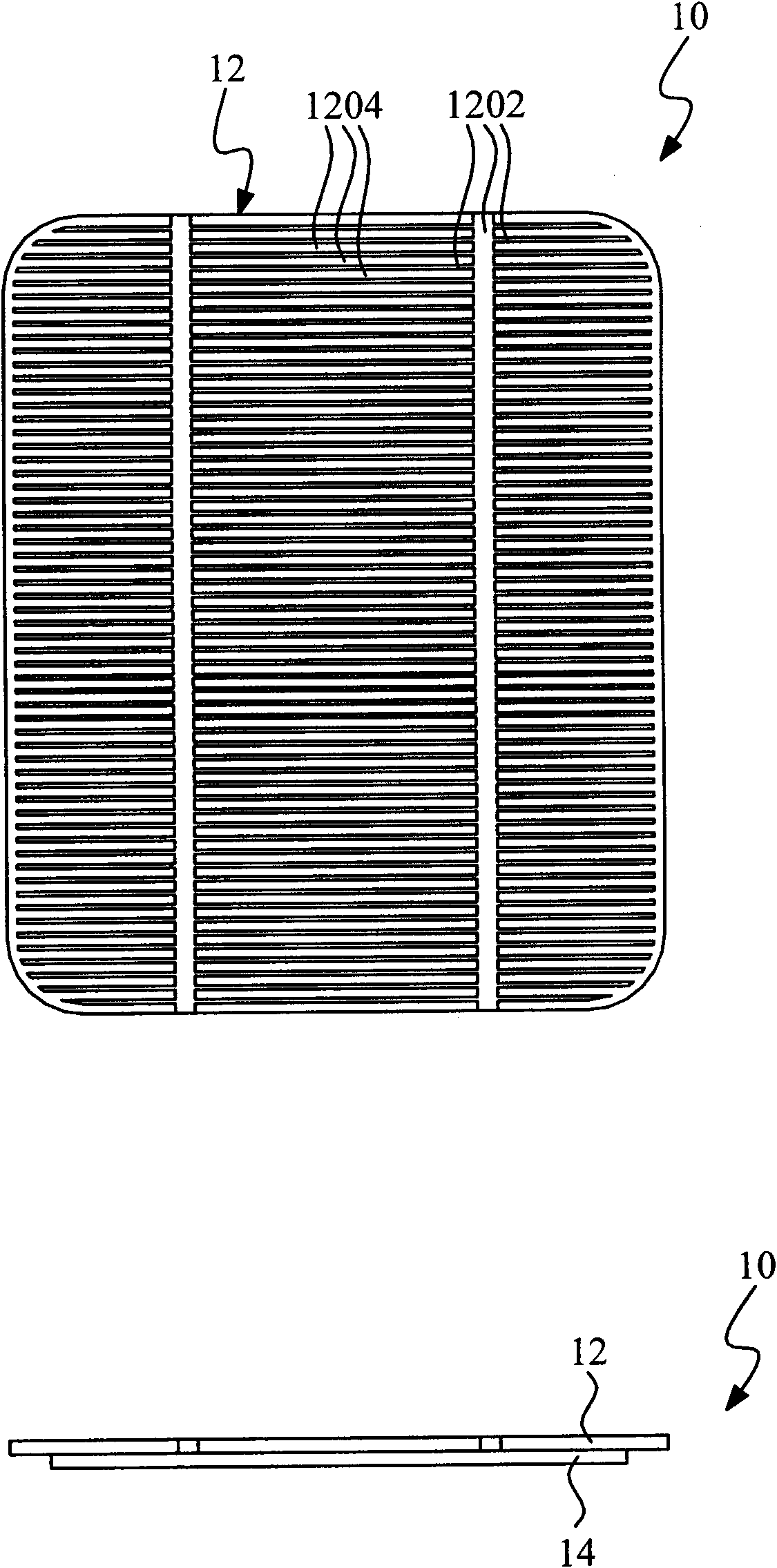
[0034] see figure 1 The appearance and side sectional view of the solar cell 10 in the present invention. It can be seen from the side sectional view that the top and bottom of the solar cell 10 are laminated by a photosensitive layer 12 and an adhesive substrate 14; it can be seen from the front view that the photosensitive layer 12 is viewed from the projection direction, and further includes a wire region 1202 As well as a silicon crystal region 1204 , whether it is polycrystalline silicon or single crystal structure, the color of the silicon crystal region 1204 is often unevenly distributed, and it requires considerable technical means to automatically classify the colors of the solar cells 10 .

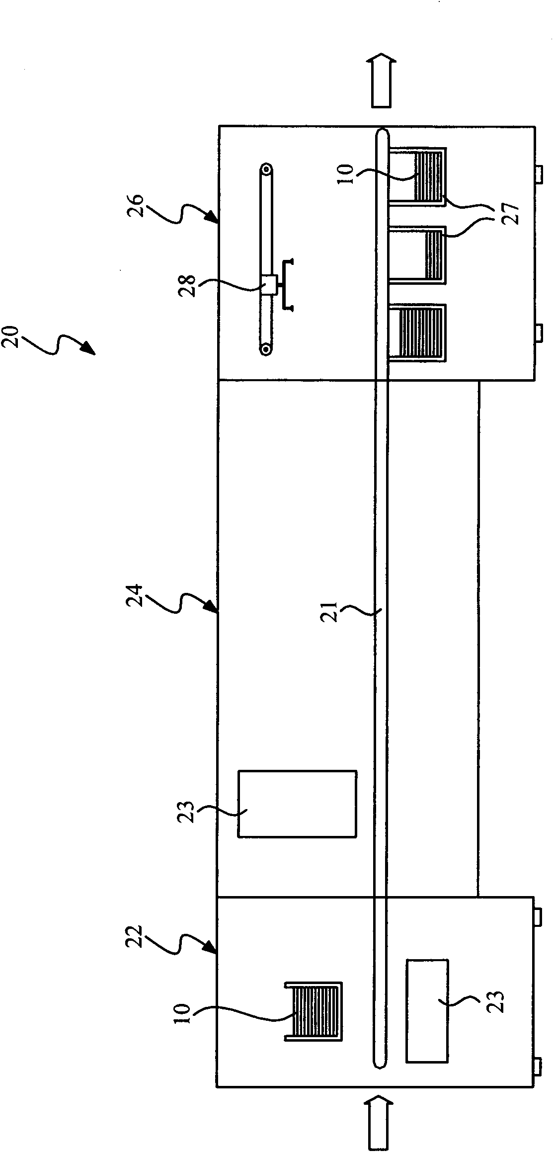
[0035] see figure 2 A schematic diagram of the automatic testing equipment 20 where the optical detection system 23 of the present invention is located. The optical detection system 23 is arranged in an automated testing equipment 20; the front section of the automated testing...


PUM


Abstract

The invention discloses an optical detecting system and a method for classifying solar cells, which performs color classification to the solar cells according to sample data. A light source equipmentirradiates solar cells, an image sensor receives reflected light to measure the colorimetric value of a plurality of pixels on an image picture of the solar cell; an image management module divides the image picture into multiple grids, and each grid contains a plurality of pixels; the image management module uses the colorimetric value of the pixel to compare with sampled data so as to classify the grids to become a classifying configuration; subsequently, the solar cells are classified according to the classifying configuration, ensuring that manufactures can automatically classify the solarcells economically, conveniently and practically according to the practical need of consumers.

Description

technical field [0001] The present invention relates to an optical inspection system and method, in particular to an optical inspection system and method for classifying solar cells. Background technique [0002] Today, when the earth's energy is gradually depleted, solar cells have become the new favorite of the generation. For silicon solar cells, the structure of the solar cell includes a layered photosensitive layer and an adhesive substrate. The visible surface of the photosensitive layer is a colored silicon crystal and wires printed on the surface of the silicon crystal. [0003] The wire color is fixed, uniform, and occupies a small area, while the silicon crystal occupies a large area. Since the crystal lattice of silicon crystal is not easy to control, especially polysilicon is more complicated, even if the same batch is originally intended to be the same color. Solar cells often have color differences between different solar cells. If they are not classified and ...

Claims


Application Information

Patent Timeline
IPC IPC(8): B07C5/342G01J3/46
Inventor 薛名凯简宏达罗文期黄建胜
Owner CHROMA ELECTRONICS SHENZHEN
Features
  • Generate Ideas
  • Intellectual Property
  • Life Sciences
  • Materials
  • Tech Scout
  • Unparalleled Data Quality
  • Higher Quality Content
  • 60% Fewer Hallucinations
Learn More