Heat sink and centrifugal fan applied by same

A centrifugal fan and heat dissipation device technology, applied to the parts of the pumping device for elastic fluid, cooling/ventilation/heating transformation, instruments, etc., can solve the problem of affecting the heat dissipation performance of the heat dissipation module 100, reducing the utilization rate of heat sinks, Uneven distribution of air volume and other issues, to achieve the effect of improving heat dissipation performance, improving utilization rate, and evenly receiving wind

Inactive Publication Date: 2010-03-24
FU ZHUN PRECISION IND SHENZHEN +1
View PDF0 Cites 10 Cited by
  • Summary
  • Abstract
  • Description
  • Claims
  • Application Information

AI Technical Summary

Problems solved by technology

[0004] like figure 1 As shown, the traditional cooling module 100 includes a fan frame 90, a rotor 98 accommodated in the fan frame 90, an air inlet 95, a first air outlet 91 and a second air outlet 92 are formed on the fan frame 90, the first The air outlet 91 and the second air outlet 92 are respectively provided with a first cooling fin group 93 and a second cooling fin group 94. When the rotor 98 rotates, the airflow generated blows to the first and second cooling fin groups 93, 94, as figure 1 In the flow field shown in , the air flow is large on the right side of the first cooling fin group 93 and small on the left side, and the air flow blowing to the second cooling fin group 94 is also large on the lower side and small on the upper side, and the air volume distribution is extremely uneven, reducing the The utilization rate of the heat sink affects the heat dissipation performance of the heat dissipation module 100

Method used


Image

  • Heat sink and centrifugal fan applied by same
  • Heat sink and centrifugal fan applied by same
  • Heat sink and centrifugal fan applied by same

Examples


Embodiment Construction

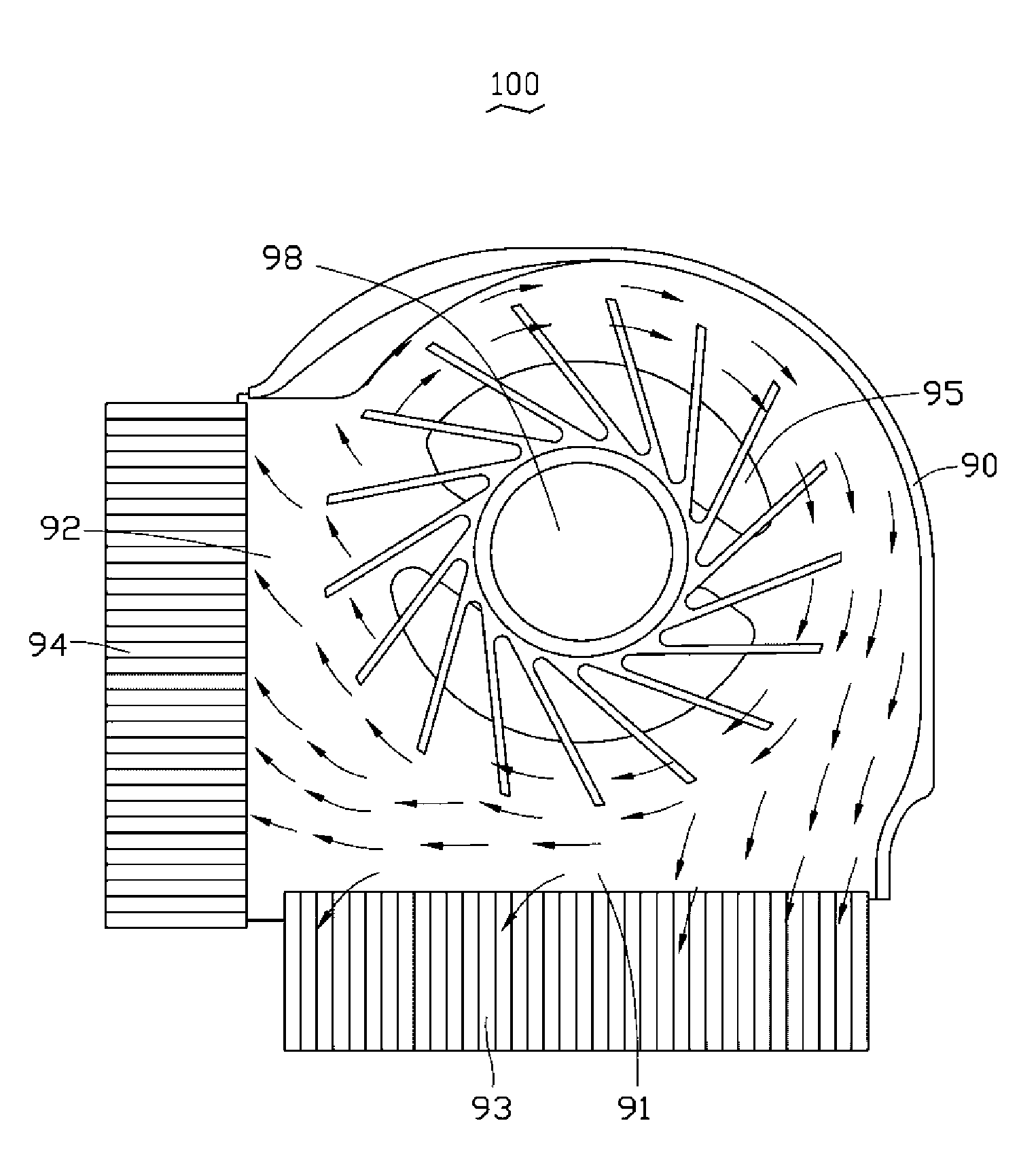
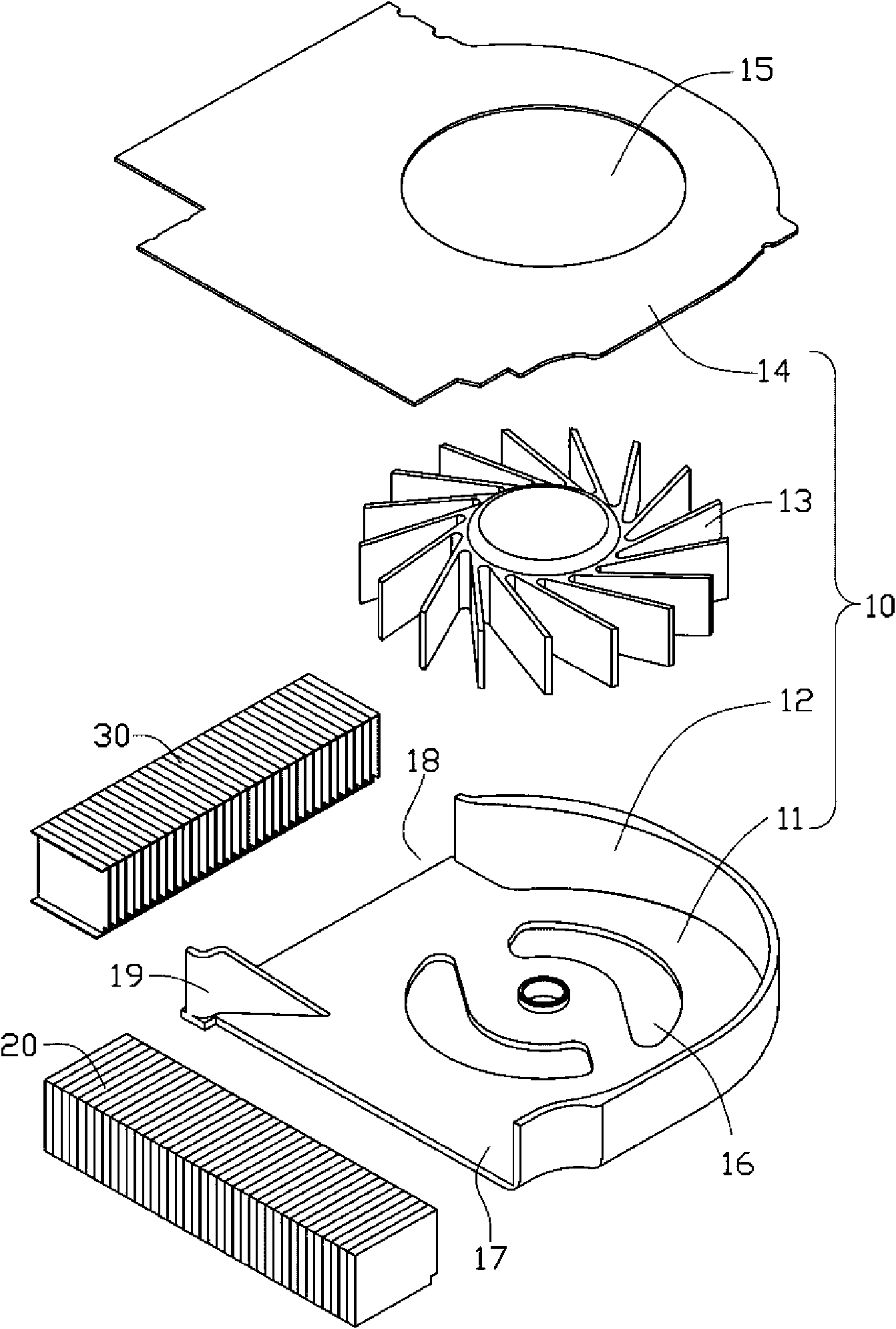
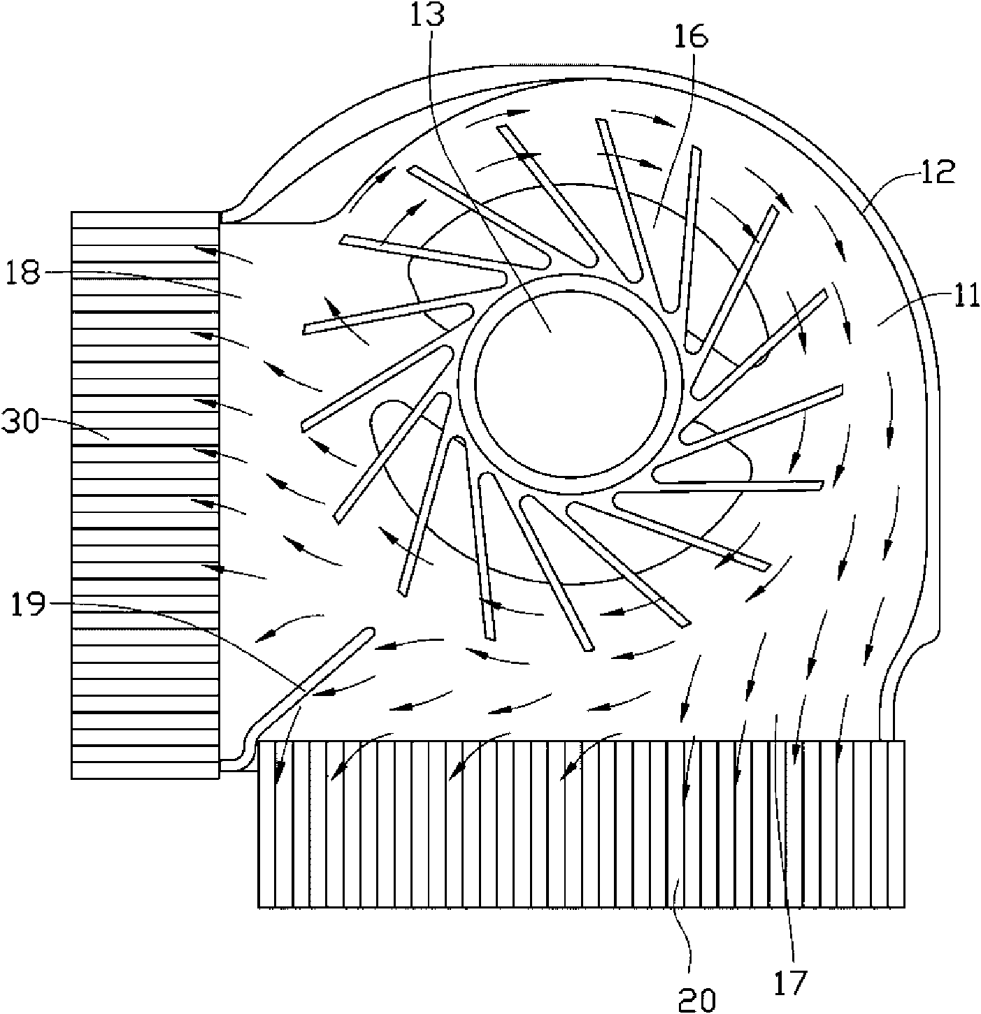
[0013] See figure 2 and image 3 The heat dissipation device includes a centrifugal fan 10, a first fin group 20 and a second fin group 30. The centrifugal fan 10 includes an impeller 13, a top plate 14, a bottom plate 11 opposite to the top plate 14, and a spiral side wall 12 arranged between the top plate 14 and the bottom plate 11.

[0014] The top plate 14, the bottom plate 11 and the side walls 12 of the centrifugal fan 10 are enclosed to form a fan frame, and an accommodating space is formed in the fan frame, and the impeller 13 is accommodated in the accommodating space. The top plate 14 is provided with a first air inlet 15 and the bottom plate 11 is provided with a second air inlet 16, the side wall 12 extends vertically upward from the periphery of the bottom plate 11 and surrounds the bottom plate 11, and the side wall 12 is provided with a first air outlet 17 and A second air outlet 18 adjacent to the first air outlet 17. The first and second air outlets 17, 18 are ...


PUM


Abstract

A heat sink comprises a centrifugal fan, a first fin group and a second fin group; the centrifugal fan comprises an impeller, a baseboard and a lateral wall surrounding the baseboard; the lateral wallis provided with a first air outlet and a second air outlet; the first fin group and the second fin group are respectively arranged at the first air outlet and the second air outlet; the air flow generated by the impeller is exhausted towards the first air outlet and the second air outlet; a lug is arranged between the first air outlet and the second air outlet; the lug extends from the exteriorof the centrifugal fan towards the interior of the centrifugal fan, changes the quantity of the air flow flowing out of the first air outlet and the second air outlet, guides the air flow towards thefirst fin group and the second fin group at the first air outlet and the second air outlet, thus ensuring the air bearing of the first fin group and the second fin group to be more even, enhancing utilization rate of fins and improving heat sinking effect.

Description

Technical field [0001] The invention relates to a heat dissipation device, in particular to a centrifugal fan. Background technique [0002] With the rapid development of the computer industry, CPUs are pursuing high-speed, high-functionality, and miniaturization, resulting in more and more serious heat dissipation problems. This is more prominent in electronic devices with small internal spaces such as notebook computers. If the heat generated by the CPU and other electronic components in the notebook computer cannot be dissipated in a timely and effective manner, the working performance of the electronic components will be greatly affected, and the service life of the electronic components will be reduced. Therefore, the electronic components must be dissipated. [0003] At present, in computers, heat dissipation modules composed of heat conductors, heat pipes, heat sinks and centrifugal fans are often used to dissipate heat from electronic components. The heat conductor is atta...

Claims


Application Information

Patent Timeline
Patent Type & Authority Applications(China)
IPC IPC(8): F04D29/44F04D17/08H05K7/20H01L23/467
CPCF04D29/422H01L23/3672F04D29/4246G06F1/203H01L23/467H01L2924/0002H01L2924/00
Inventor 黄清白赵志辉
Owner FU ZHUN PRECISION IND SHENZHEN
Why Eureka
Try Eureka