Optical encoder

一种编码器、光电式的技术,应用在仪器、采用光学装置、采用光学装置传递传感构件等方向,能够解决难基准同步、主增量信号失去原形、难检测器小型化等问题,达到鲁棒性高、低成本的效果

Active Publication Date: 2010-03-24
MITUTOYO CORP
View PDF2 Cites 23 Cited by
  • Summary
  • Abstract
  • Description
  • Claims
  • Application Information

AI Technical Summary

Problems solved by technology

[0005] However, in order to increase the averaging effect, it is necessary to expand the detection range, making it difficult to miniaturize the detector
On the other hand, when the ruler period is set to a narrow period, the filter effect is reduced
In addition, since the main incremental signal loses its original shape, it is difficult to perform accurate reference synchronization.

Method used


Image

  • Optical encoder
  • Optical encoder
  • Optical encoder

Examples


Embodiment Construction

[0050] Hereinafter, embodiments of the present invention will be described in detail with reference to the drawings.

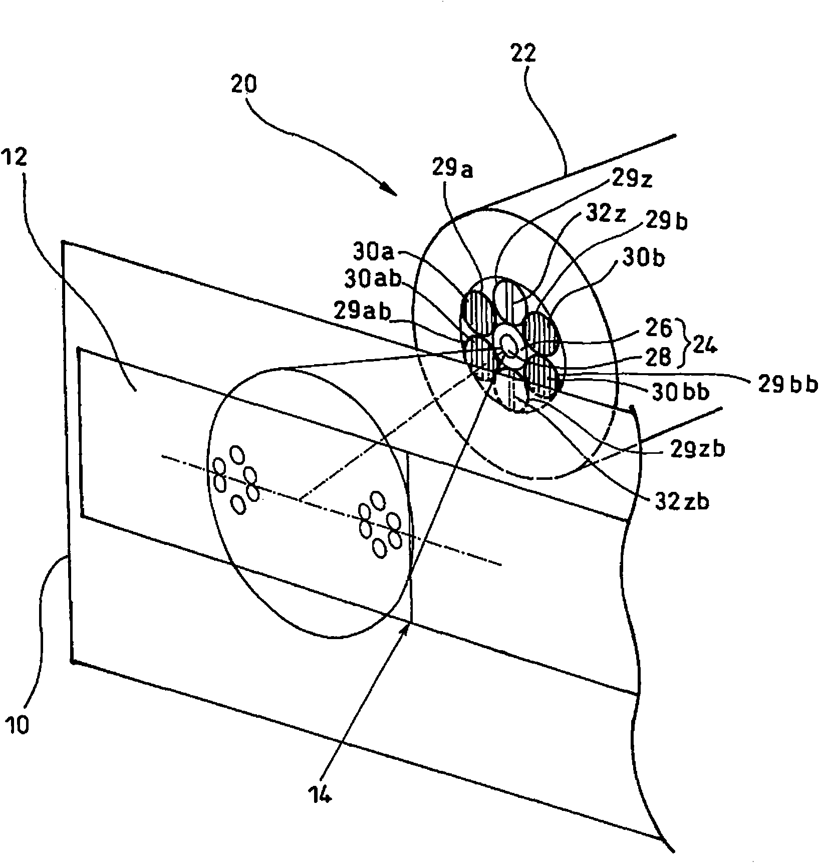
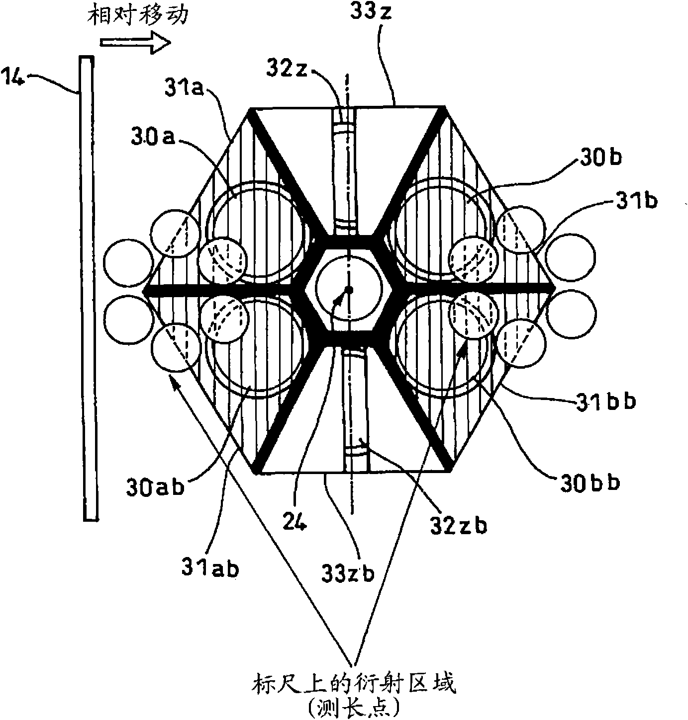
[0051] figure 1 (stereo view) and figure 2 (A plan view viewed from the scale side) shows the structures of the scale 10 and the detector 20 in the first embodiment of the present invention.

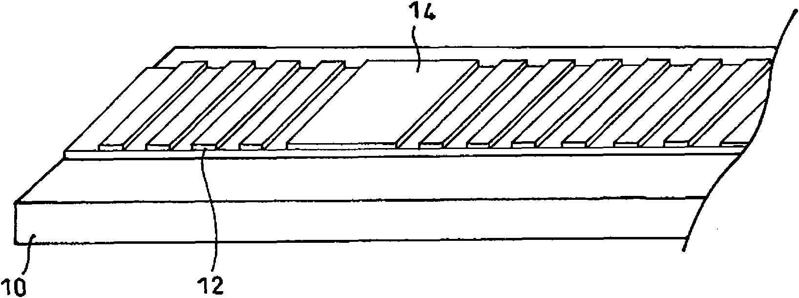
[0052] exist image 3 As shown in detail in , the above-mentioned scale 10 has: an incremental track 12, which is composed of a reflective phase grating; At the end for detection by the detector 20 , it is formed by a reflective slit parallel to the phase grating of the incremental track 12 . The reference mark 14 can be set as, for example, Figure 4 A grating-integrated structure as shown in (a) or Figure 4 Additional structure as shown in (b). Here, the width Wo of the reference mark 14 is figure 2 The width Wz of the light-receiving differential slits 33z, 33zb of the reference detection light-receiving parts 32z, 32zb shown (refer to Figure 5 ), and needs...


PUM


Abstract

In an optical encoder for measuring relative displacement, a scale 10 has a reference mark 14 composed of a reflection slit formed on at least one point of an incremental track 12, a detection portion(20) has a light irradiation portion (24), main light receiving portions 30a, 30b, 30ab and 30bb that are disposed at the surrounding centering around the corresponding light irradiation portion andoutput incremental signals four phases of which are different from each other, and a pair of reference signal light receiving portions 32z and 32zb that are disposed in the direction perpendicular tothe length measurement direction using the light irradiation portion as the center of point symmetry, and a signal processing portion 40 has a three-phase signal generation portion 48, a quadrature sine wave signals generation portion 50, a direction judgment circuit 56, an internal period counter 58, and a reference signal processing portion 60, thereby bringing about a micro-sized optical encoder capable of detecting the reference.

Description

technical field [0001] The present invention relates to a kind of photoelectric encoder (optical encoder), particularly relates to a kind of photoelectric encoder applicable as the sensor of length measurement such as laser interference length measuring instrument, this photoelectric encoder has A main scale having an incremental track of a reflective phase grating (reflective phase grating) and a detection unit for relative displacement to the main scale are formed. Background technique [0002] In an incremental photoelectric encoder, when the detection range is reduced by downsizing the detector, it is difficult to separate a reference mark for detecting the origin (reference point) from an incremental rail of the main scale. Even if the separation can be performed in a minute range, the configuration (calibration adjustment) of the detector becomes difficult, resulting in damage to the encoder performance. In addition, when the incremental rail and the reference mark ar...

Claims


Application Information

Patent Timeline
Patent Type & Authority Applications(China)
IPC IPC(8): G01D5/36G01B11/02
CPCG01D5/38
Inventor 高桥知隆
Owner MITUTOYO CORP
Why Eureka
Try Eureka