Liquid crystal panel shift apparatus and method

A liquid crystal panel and transfer device technology, applied in the direction of instruments, chucks, manipulators, etc., can solve the problems of liquid crystal panel 2 damage, increase the tact time of screen acquisition, etc., reduce production costs, improve production efficiency and yield, simplify Effects of complex manipulation processes

Active Publication Date: 2010-03-24
K TRONICS (SUZHOU) TECH CO LTD +1
View PDF0 Cites 16 Cited by
  • Summary
  • Abstract
  • Description
  • Claims
  • Application Information

AI Technical Summary

Problems solved by technology

[0005] In the above-mentioned whole process of tearing the film of the liquid crystal panel 2, the three independent moving parts of the turning machine 3, the transfer machine 4, and the mobile workbench 5 are likely to cause liquid crystals due to poor vacuum adsorption during the mutual transfer of the liquid crystal panel 2. The panel 2 is damaged; the transfer of the liquid crystal panel 2 from the tray 1 to the mobile workbench 5 needs multiple actions of the device to complete, and the actions will wait for each other, such as: after the inversion machine 3 completes the inversion, the transfer machine 4 will Move from the original position to the top of the flipper 3, and the flipper 3 will start the next action after the transfer machine 4 finishes picking up the screen and returns to the original point. Bottleneck in module assembly process takt time

Method used


Image

  • Liquid crystal panel shift apparatus and method
  • Liquid crystal panel shift apparatus and method
  • Liquid crystal panel shift apparatus and method

Examples


Embodiment 1

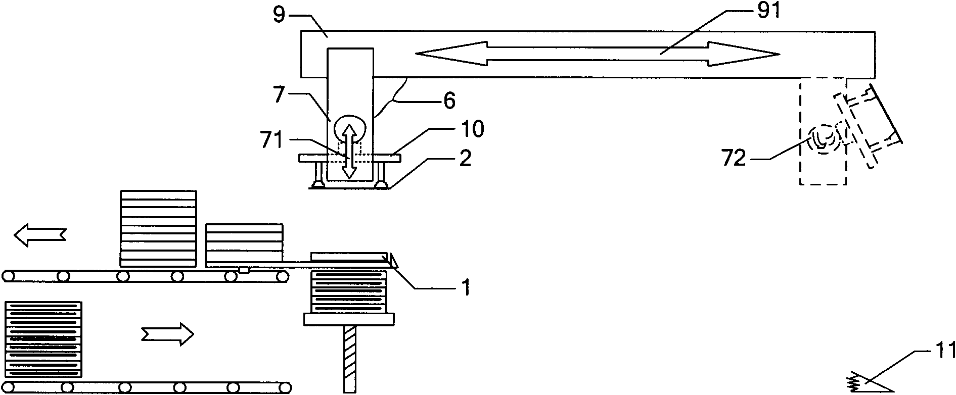
[0028] In the transfer and turning machine 6 included in the above-mentioned liquid crystal panel transfer device for completing the process of absorbing, transporting and rotating the liquid crystal panel to the operating position, as figure 2 As shown, it can specifically include:

[0029] The first piston device 7 comprises a linear cylinder 71, a piston of the linear cylinder 71, a rotary cylinder 72 and a piston of the rotary cylinder 72, and one end of the piston of the rotary cylinder 72 of the first piston device 7 is connected to a liquid crystal panel (Panel) 2 for adsorption. Mechanical arm 10; Wherein, the piston of linear cylinder 71 is connected with rotary cylinder 72, and first piston device 7 is vertically placed with linear cylinder 71 axial direction;

[0030] The second piston device 9 comprises the piston of a linear cylinder 91 and the linear cylinder 91, the second piston device 9 is perpendicular to the first piston device 7, and the piston of the line...

Embodiment 2

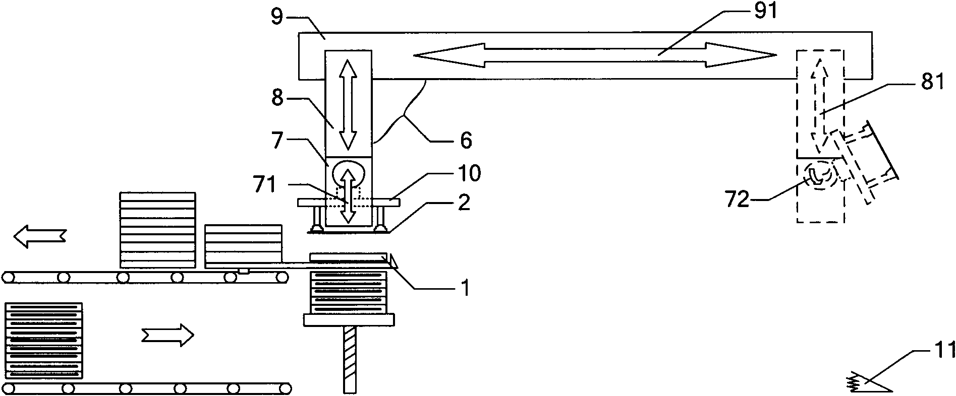
[0037] image 3 It is a structural schematic diagram of another liquid crystal panel transfer device of the present invention. Such as image 3 As shown, the present invention provides another liquid crystal panel transfer device, which differs from the second embodiment above in that a third piston device 8 is added, including a linear cylinder 81 and a piston of the linear cylinder 81 . The setting of the third piston device 8 is for the two transfer and turning machines 6 to reciprocate alternately at two different heights.

[0038] The transfer and turning machine 6 included in the liquid crystal panel transfer device for completing the process of absorbing, transporting and rotating the liquid crystal panel to the operating position can also specifically include:

[0039] The first piston device 7 comprises a linear cylinder 71, a piston of the linear cylinder 71, a rotary cylinder 72 and a piston of the rotary cylinder 72, and one end of the piston of the rotary cylind...

Embodiment 3

[0048] Figure 4 It is a flow chart of the liquid crystal panel transfer method of the present invention. Such as figure 2 , Figure 4 As shown, the specific steps include:

[0049] Step 401, absorbing the horizontally placed liquid crystal panel and moving it up to the first height position;

[0050] Specifically, the piston of the linear cylinder 71 of the first piston device 7 is located at the lower end of the linear cylinder 71, and the mechanical arm 10 connected to the piston of the rotary cylinder 72 of the first piston device 7 vacuum-adsorbs the liquid crystal panel (Panel) 2, wherein the linear cylinder The piston of 71 is connected with rotary cylinder 72, and the piston of the linear cylinder 71 of the first piston device 7 moves to the upper end of the linear cylinder 71, and the mechanical arm 10 also moves to the first height position along with the piston of the linear cylinder 71.

[0051] Step 402, moving the liquid crystal panel horizontally;

[0052]...


PUM


Abstract

The invention discloses a liquid crystal panel shift apparatus and method. The method includes: combining the conventional turning machine and shifting machine independently turning and shifting themoving parts of the liquid crystal panel into a moving part turning and shifting machine of the invention; simultaneous shifting the film removing action from a movable workbench to the turning and shifting machine, to omit the transmission action from the shifting machine to the movable workbench in the conventional apparatus and setting up a pedal, for releasing adsorption after removing the film, taking down the liquid crystal panel, and then, the liquid crystal panel shift apparatus backing to the original position, to complete the whole process of actions. The inventive liquid crystal panel shift apparatus avoids the defect that liquid crystal panel is easy to be damaged in the mutual transmission process of the three independent moving parts (a turning machine a shifting machine anda movable workbench) in the conventional apparatus due to bad vacuum suction, to improve the production efficiency and yield of LCD.

Description

technical field [0001] The invention relates to a module assembly process in the liquid crystal display industry, in particular to a liquid crystal panel transfer device and method. Background technique [0002] In recent years, Liquid Crystal Display (LCD for short) has attracted much attention due to its thinness, good color reproduction, convenient color management, good brightness uniformity, long life, safety, environmental protection, good shock resistance, etc. Advantages, it has been widely used in small and medium-sized liquid crystal panel display devices. The liquid crystal display module of the LCD is mainly composed of two parts: a liquid crystal panel (Panel) which is used to display pictures but cannot emit light itself, and a backlight unit (BLU for short) which provides light for it to make it visible. In the production process, the two parts need to be assembled together through a module assembly (Module Assembly) process to make a liquid crystal display m...

Claims


Application Information

Patent Timeline
Patent Type & Authority Applications(China)
IPC IPC(8): G02F1/1333B25J3/04B25J15/06
Inventor 张建中
Owner K TRONICS (SUZHOU) TECH CO LTD
Why Eureka
Try Eureka