
Small-diameter deep hole drill and fine deep hole processing method

A processing method and small-diameter technology, applied in boring/drilling, drilling/drilling equipment, metal processing, etc., can solve the problems of inability to process deep holes, breakage of small-diameter drills, and deterioration of hole straightness, etc. problems, to achieve the effect of good flatness, improved inner surface roughness, and excellent flatness

Inactive Publication Date: 2010-03-24
MOLDINO TOOL ENG LTD
View PDF5 Cites 21 Cited by
  • Summary
  • Abstract
  • Description
  • Claims
  • Application Information

AI Technical Summary

Problems solved by technology

During this time, the chips move to the end of the groove due to the influence of the twist of the groove, and adhere to the back of the drill head and between the outer peripheral surface of the neck and the inner peripheral surface of the machined hole, and apply vibration to the drill bit during cutting. Deterioration of straightness, or breakage of small diameter drill bits
Especially when the groove is relatively long and the rigidity is lost, the flatness etc. will deteriorate significantly and there is a risk of breakage when processing a small diameter deep hole.
Furthermore, even if the groove is set shorter in order to improve the mechanical strength, as long as the drill diameter is less than 1mm, the chips will flow to the rear of the drill head, and it is easy to adhere to the processing hole, making it impossible to perform deep hole processing.

Method used


Image

  • Small-diameter deep hole drill and fine deep hole processing method
  • Small-diameter deep hole drill and fine deep hole processing method
  • Small-diameter deep hole drill and fine deep hole processing method

Examples


Embodiment 1

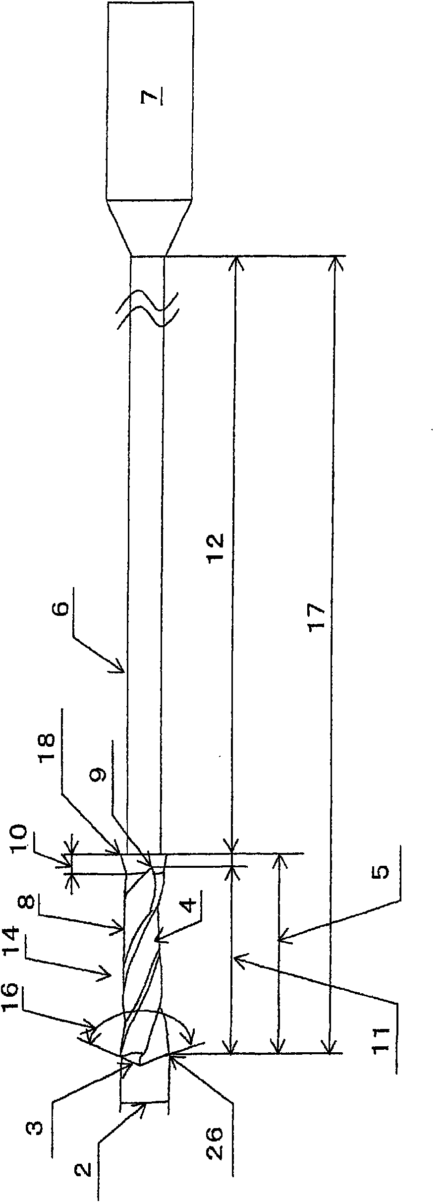
[0207] As an example of the present invention and a comparative example, a drill with 2 flutes, a drill diameter of 0.2 mm, a groove twist angle of 30 degrees, a web thickness of 0.07 mm (35% of the drill diameter), a shank diameter of 3 mm, and a drill head of 5 For a drill with a length of 1.1mm, the groove length, the reduction of the outer diameter (the amount of reverse taper), the outer diameter of the end of the groove, and the maximum diameter of the tapered diameter expansion part arranged in a straight line, etc., were produced as shown in Table 1. Several kinds. In Table 1, the length of the groove, the outer diameter of the end of the groove, and the maximum diameter of the tapered diameter-enlarged portion arranged in a straight line represent magnifications corresponding to the diameter of the drill. The base material of the drill bit is an ultrafine particle cemented carbide with an average particle size of WC of 0.6 μm or less and a Co content of 13w%, and AlCr...

Embodiment 2

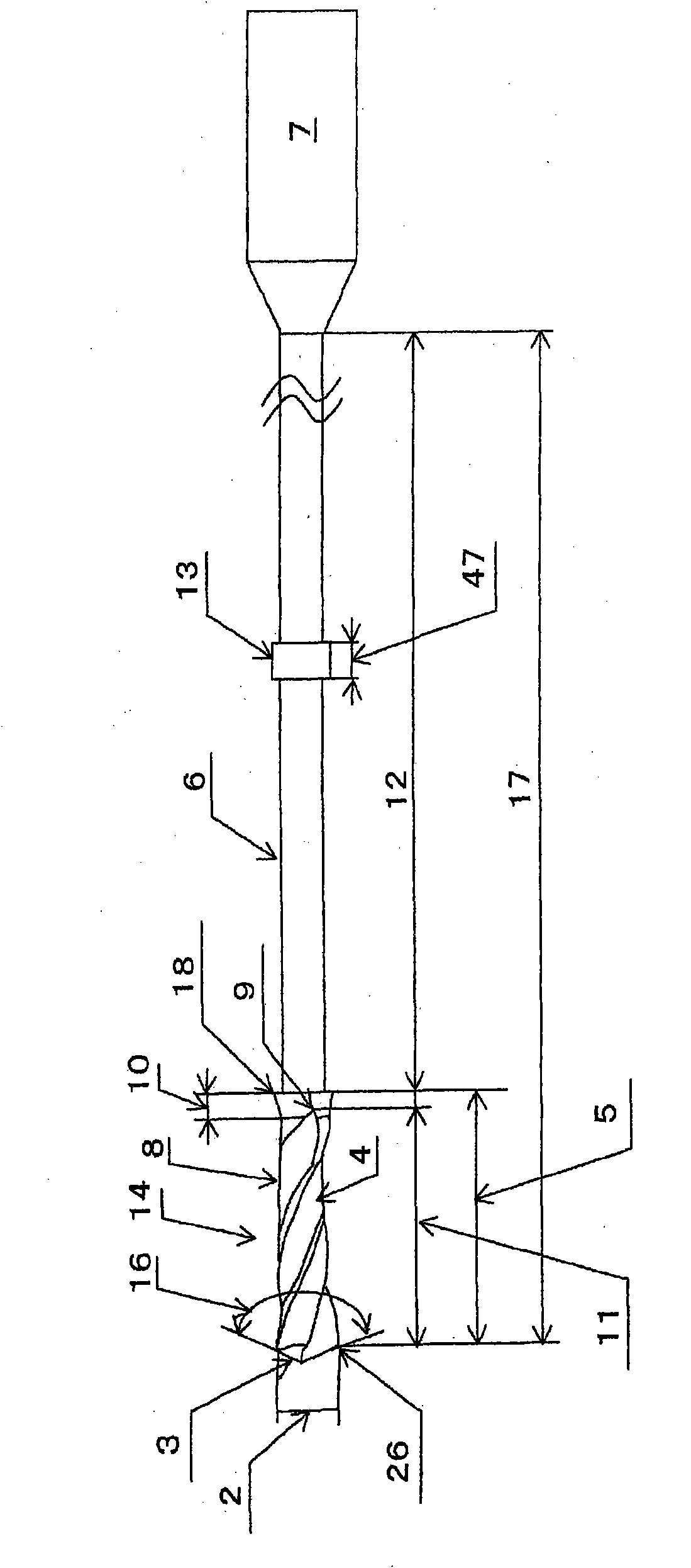
[0215] As an example of the present invention and a comparative example, two flutes, a drill diameter of 0.2 mm, a drill head of 1.1 mm, a neck length of 9.0 mm, a total length of 40 mm, a groove twist angle of 30 degrees, and a web thickness of 0.07 mm (35% of the drill diameter), the diameter of the shank is 3 mm, and the guide is set at a position 2.0 mm away from the cutting edge of the neck. Several types are produced as shown in Table 1, such as the reduced diameter of the diameter (the amount of reverse taper), the outer diameter of the groove end, and the maximum diameter of the tapered enlarged diameter part arranged in a straight line. The base material of the drill bit is an ultrafine particle cemented carbide with an average particle size of WC of 0.6 μm or less and a Co content of 13w%, and AlCrN films are coated on the drill head and neck.

[0216] The test conditions are as follows: a rectangular block material of SUS304 is prepared as the material to be cut, an...

Embodiment 3

[0224]Next, a sample having a neck length of 15 mm, a total length of 50 mm, and a change in the interval between the guide portions was produced with the same specifications as in Example B5 of the present invention. The test conditions are: the depth of the processed hole is 10mm (80 times the diameter of the drill bit) of the through hole, and the others are the same as in Example 2. Evaluation was the same as in Example 2. The results are shown in Table 3.

[0225] 【table 3】

[0226]

[0227] As a result, due to the effect of the guides provided on the neck, Inventive Examples B30 to B32 having guides at intervals of 1.0 mm to 2.0 mm can process holes with good straightness of 10 μm or less.

[0228] On the contrary, in Comparative Example B33 and Comparative Example B34, sufficient flatness could not be obtained. It is estimated that this may be due to the small interval between the guide parts, which partially increases the cutting resistance, and the flatness cann...


PUM


Abstract

A small-diameter drill for deep hole drilling is provided which is capable of inhibiting the cutting chips from getting bitten and producing a straightness for a drilled hole, thus suitable for drilling a hole having a depth (L) which is 15 or more times the diameter (D) of a drilled hole. The small-diameter drill 1 has a diameter 2 which is 1 mm or less and a drill section 5 including cutting edge(s) 3 and flute(s) 4. The length 11 of the flute 4 is at least 5 times and at most 10 times the drill diameter 2. The diameter of the drill section 5, after being reduced in diameter from the cutting edge 3 toward the rear of the drill section 5, is expanded in diameter so that the outer diameter at the end of the flute 4 becomes at least 0.9 times and at most 0.98 times the drill diameter 2. Anexpanded-diameter portion 10 is provided between the drill section 5 and a neck section 6 connected to a shank 7 and is expended in diameter from the outer diameter at the end 9 of the flute 4 up to 1 or less times the drill diameter 2. The diameter of the neck section 6 is smaller than the drill diameter 2, and the length 12 of the neck section 6 is 10 or more times the drill diameter 2.

Description

technical field [0001] The present invention relates to a new-shaped small-diameter drill for deep-hole machining with a drill diameter of 1 mm or less and used for machining molds and parts, and a fine deep-hole machining method using the above-mentioned small-diameter drill for deep-hole machining. When the processing hole diameter (hereinafter referred to as D) is less than 1mm, and the ratio L / D to the processing hole depth (hereinafter referred to as L) is more than 15 times the deep hole and through hole, it can process the L / D of 10 with high precision. times more than 2 times, especially the extremely deep holes whose L / D is more than 50 times. The invention relates to a small-diameter drill bit for deep hole processing and a fine deep hole processing method which are respectively adapted to thin and deep non-through holes and through holes. Background technique [0002] When the tool protrusion length corresponding to the drill diameter is long, the rigidity of the...

Claims


Application Information

Patent Timeline
Patent Type & Authority Applications(China)
IPC IPC(8): B23B51/00
CPCB23B35/00B23B2270/56B23B2251/54B23B2251/422B23B2251/245B23B2251/56B23B51/02B23B2251/426B23B2251/248Y10T408/23Y10T408/9097Y10T408/03Y10T408/5586Y10T409/303808Y10T408/9095B23B51/0411B23B51/063B23B51/011B23B51/00B23B39/00B23B41/00
Inventor 近藤芳弘赤松猛史
Owner MOLDINO TOOL ENG LTD
Learn More