Vibration-suppressing mechanism for gear-shaping machine

一种减振机构、加工机床的技术,应用在金属加工机械零件、切齿机、带有齿的元件等方向,能够解决加工精度影响等问题,达到减小机械振动的效果

Active Publication Date: 2010-03-24
MITSUBISHI HEAVY IND MACHINE TOOL CO LTD
View PDF0 Cites 7 Cited by
  • Summary
  • Abstract
  • Description
  • Claims
  • Application Information

AI Technical Summary

Problems solved by technology

Said vibrations can negatively affect machining accuracy

Method used


Image

  • Vibration-suppressing mechanism for gear-shaping machine
  • Vibration-suppressing mechanism for gear-shaping machine
  • Vibration-suppressing mechanism for gear-shaping machine

Examples


Embodiment Construction

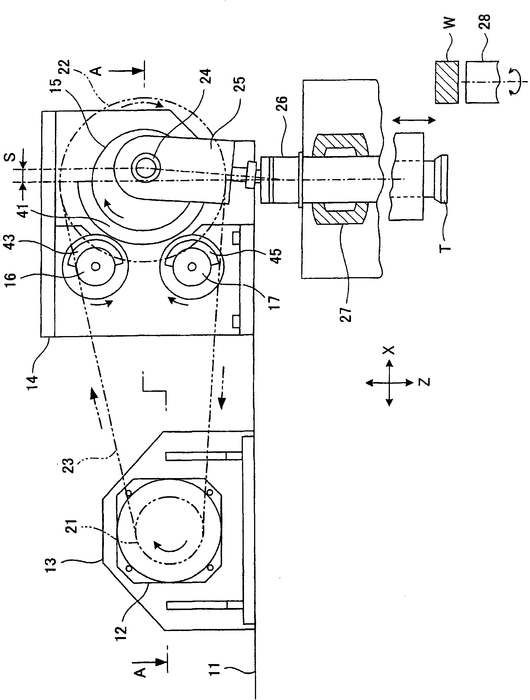
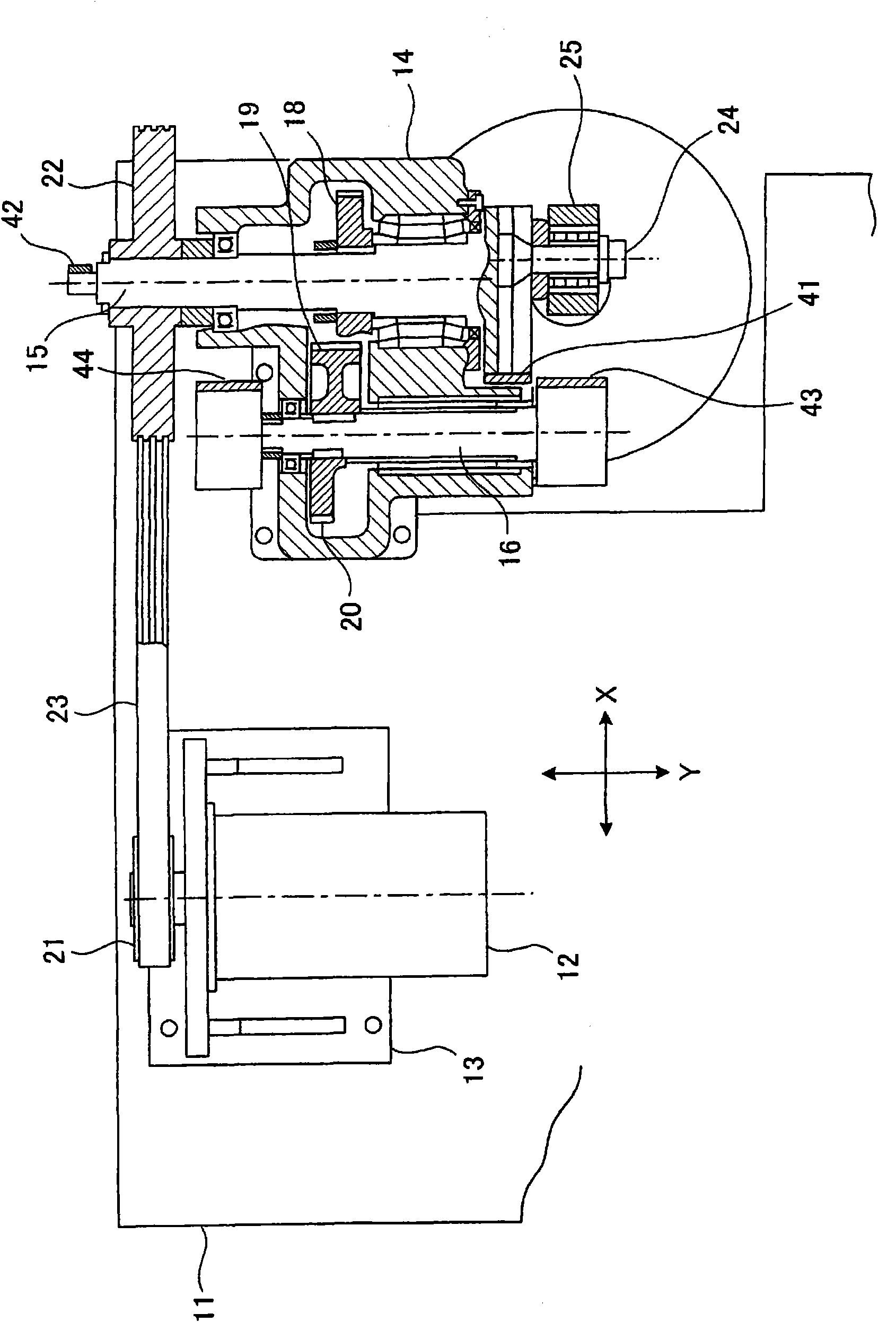
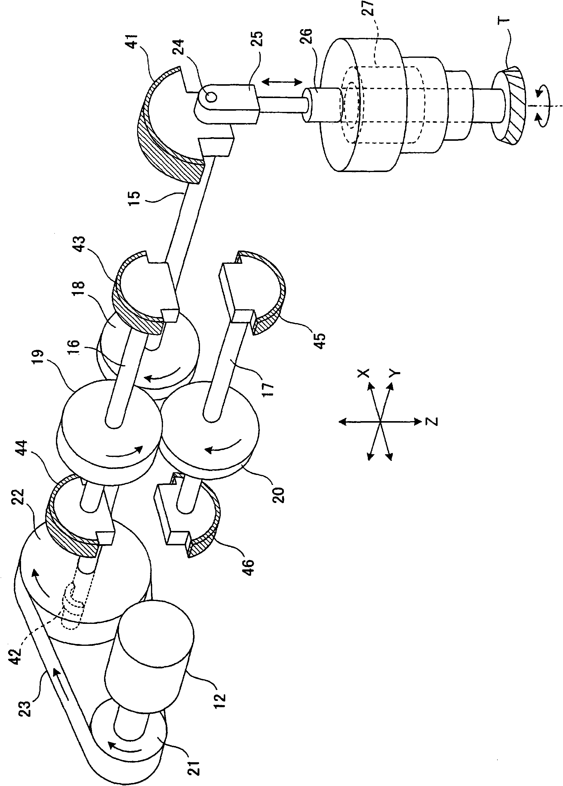
[0032] A vibration damping mechanism for a gear processing machine tool according to the present invention will be described in detail below with reference to the accompanying drawings. figure 1 is a front view illustrating a vibration damping mechanism for a gear processing machine tool according to an embodiment of the present invention. figure 2 is along figure 1 Cross-sectional view of arrow line A-A. image 3 It is the basic structural diagram of the damping mechanism. Figure 4 It is a front view illustrating the basic principle of the damping mechanism. Figure 5 is a top view illustrating the basic principle of the vibration damping mechanism.

[0033] equipped with Figure 1-3 The gear processing machine tool of the vibration damping mechanism shown is a gear shaping machine that shapes a workpiece W into, for example, a helical gear. Note that the X-axis, Y-axis, and Z-axis in the figure are three axes that cross each other perpendicularly. The X-axis directio...


PUM


Abstract

This aims to provide a vibration-suppressing mechanism for a gear-shaping machine, which is enabled to suppress mechanical vibrations at the time of shaping a helical gear by selecting an optimum balance weight. The vibration-suppressing machine is provided for the gear-shaping machine which performs the gear shaping on a work (W) with a cutter (T) mounted on a main spindle (26) of crank reciprocations. The vibration-suppressing machine comprises balance shafts (16 and 17) juxtaposed with respect to a crankshaft (15), for rotating at an identical rotation speed in synchronism with the crankshaft (15) and in the same and opposite directions as and to that of the crankshaft (15), main balance weights (41 and 42) removably mounted on the crankshaft (15), for suppressing the axial vibrations of the main spindle (26), and auxiliary balance weights (43 to 46) removably mounted on the balance shafts (16 and 17), for suppressing the vibrations of in directions perpendicular to the axial direction of the main spindle (26). Those individual balance weights (41 to 46) are selected on the basis of leads meeting the stroke width of the main spindle (26) and the torsional angle of the work (W).

Description

technical field [0001] The present invention relates to a vibration damping mechanism for a gear machining machine tool for performing gear machining on a gear blank using a rotary tool connected to a main shaft manufactured to be reciprocable by a crank mechanism. Background technique [0002] A gear machining machine tool, such as a gear shaping machine, is provided as a conventional machine tool to perform gear machining on a gear blank using a rotary tool. When this type of gear machining machine is used, a workpiece (gear blank) is formed into a desired gear by intermeshing a rotating cutter (rotary tool) with a rotating workpiece and then reciprocating the cutter in the axial direction of the workpiece shape. [0003] The reciprocating movement of the tool is achieved by moving a spindle connected to the tool in its axial direction by moving a crank mechanism. However, such reciprocating motion of the spindle generates vibration in the machine tool due to the interna...

Claims


Application Information

Patent Timeline
Patent Type & Authority Applications(China)
IPC IPC(8): B23F5/16
CPCB23Q11/0035B23F23/00B23F5/16B23F23/10Y10T74/2183Y10T74/2184Y10T408/3796Y10T409/100636
Inventor 东川隆英丸山和孝
Owner MITSUBISHI HEAVY IND MACHINE TOOL CO LTD
Why Eureka
Try Eureka