Substrate supporting mechanism

A technology for a substrate and a holding surface, applied in the field of manipulators, can solve the problems of transporting the substrate to the correct position, unable to obtain the substrate W to slide, unable to crack the substrate, etc.

Inactive Publication Date: 2010-03-24
ULVAC INC
View PDF4 Cites 12 Cited by
  • Summary
  • Abstract
  • Description
  • Claims
  • Application Information

AI Technical Summary

Problems solved by technology

However, when the temperature is high (for example, 300 to 500° C.), there will be a problem that the holding part 5 is deformed by heat or melted, and as a result, the effect of preventing the substrate W from slipping cannot be obtained.
[0006] On the other hand, in the case of low temperature (below 200°C), there will also be a problem th

Method used


Image

  • Substrate supporting mechanism
  • Substrate supporting mechanism
  • Substrate supporting mechanism

Examples


Embodiment

[0039] Next, an embodiment of the present invention will be described. In this embodiment, a substrate (wafer size: 300 mm) is used for a transfer test using a substrate transfer robot, and the positional deviation of the substrate relative to the end effector is measured. .

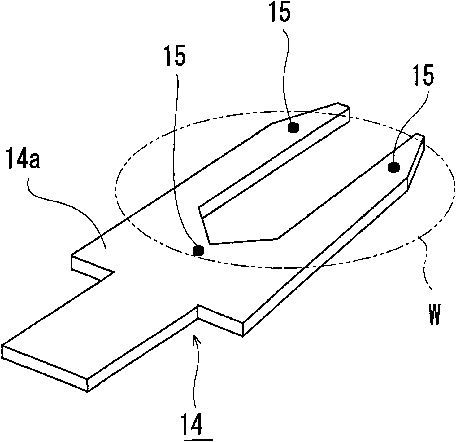
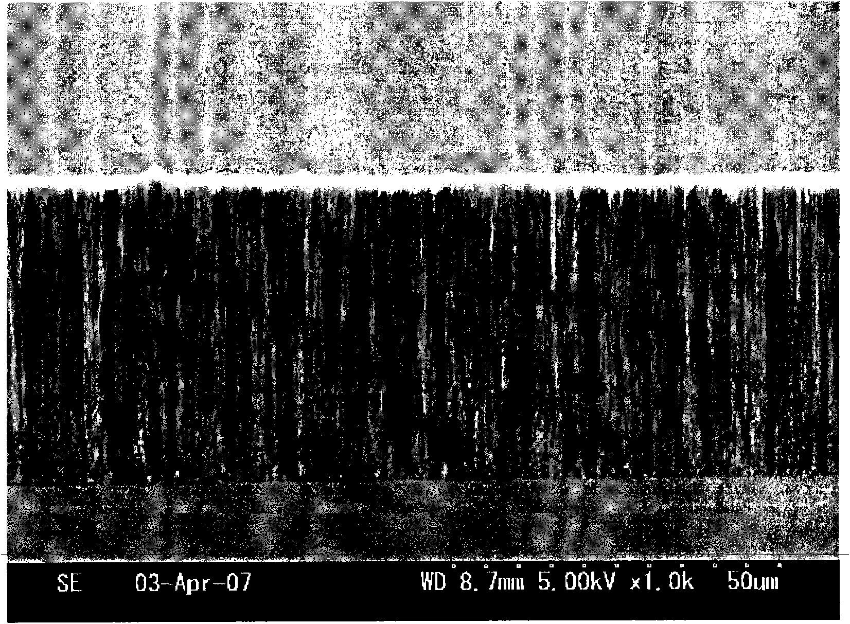
[0040] The end effector is made of aluminum oxide, and its upper surface is mounted with figure 1 and figure 2 The carbon nanotube holding part 15 shown in , the installation position of the holding part is figure 1 The 3 locations shown are 2 locations at the tip of the bifurcation and one location at the base of the bifurcation. The holding part adopts a structure in which carbon nanotubes are grown on a silicon wafer, and the growth conditions of the carbon nanotubes are the same as those of figure 2 The samples shown were grown under the same conditions. The total area of ​​the holding part is 11.5cm 2 .

[0041] The handling test is to let the robot repeatedly perform the following actions...


PUM


Abstract

The invention provides a substrate supporting mechanism which can achieve high speed conveyance of a substrate while ensuring proper conveyance operation. In the substrate supporting mechanism,a holding portion (15) made of carbon nano tubes is installed on the supporting surface (14a) of an end effector (14), and a substrate (W) is supported by the distal ends of the carbon nano tubes. An intermolecular force is generated between the substrate and the carbon nano tube and the substrate is supported with a fixed suction force to the supporting surface. The suction force is generated both in the atmosphere and in the vacuum and a bigger force is obtained for a larger number of carbon nano tubes perunit area. With such an arrangement, slip of a conveyance article on the supporting surface can be suppressed effectively and high speed conveyance of a substrate can be attained. Since the carbon nano tube is excellent in heat resistance, poor conveyance due to deterioration or sticking of the holding portion by heat is prevented during use under high temperature environment and proper conveyance operation of substrate can be ensured.

Description

technical field [0001] The present invention relates to a substrate holding mechanism, which is applied, for example, to a manipulator used to transport semiconductor substrates. Background technique [0002] From the point of view of the prior art, in the field of semiconductor manufacturing, a substrate handling robot with a multi-articulated arm is used to transport a substrate. Figure 7 It is a perspective view showing a general structure of such a conventional substrate transfer robot. The substrate transfer robot 1 includes: a driving unit 2 ; an arm 3 having a multi-joint structure connected to the driving unit 2 ; and an end effector 4 (hand) connected to the front end of the arm 3 . The end effector 4 uses its upper surface to support the back surface of the substrate, and performs substrate transfer between a plurality of processing chambers such as a film forming chamber and an etching chamber, or transfers substrates to a stage and a substrate storage box. [0...

Claims


Application Information

Patent Timeline
IPC IPC(8): B65G49/07B25J15/08H01L21/677
CPCH01L21/6838
Inventor 武者和博南展史川口崇文村上裕彦中野美尚江上洋一
Owner ULVAC INC
Why Eureka
Try Eureka