Armature stroke adjustment for solenoid valve

A solenoid valve and armature technology, which is applied to fuel injection devices, special fuel injection devices, charging systems, etc., can solve problems such as sensitive tolerances and long distances.

Inactive Publication Date: 2010-03-24
ROBERT BOSCH GMBH
View PDF1 Cites 10 Cited by
  • Summary
  • Abstract
  • Description
  • Claims
  • Application Information

AI Technical Summary

Problems solved by technology

In this case, a considerably longer and therefore also significantly tolerance-sensitive tolerance chain results for the distance between the sealing seat in the valve body and the upper stroke stop.

Method used


Image

  • Armature stroke adjustment for solenoid valve
  • Armature stroke adjustment for solenoid valve
  • Armature stroke adjustment for solenoid valve

Examples


Embodiment Construction

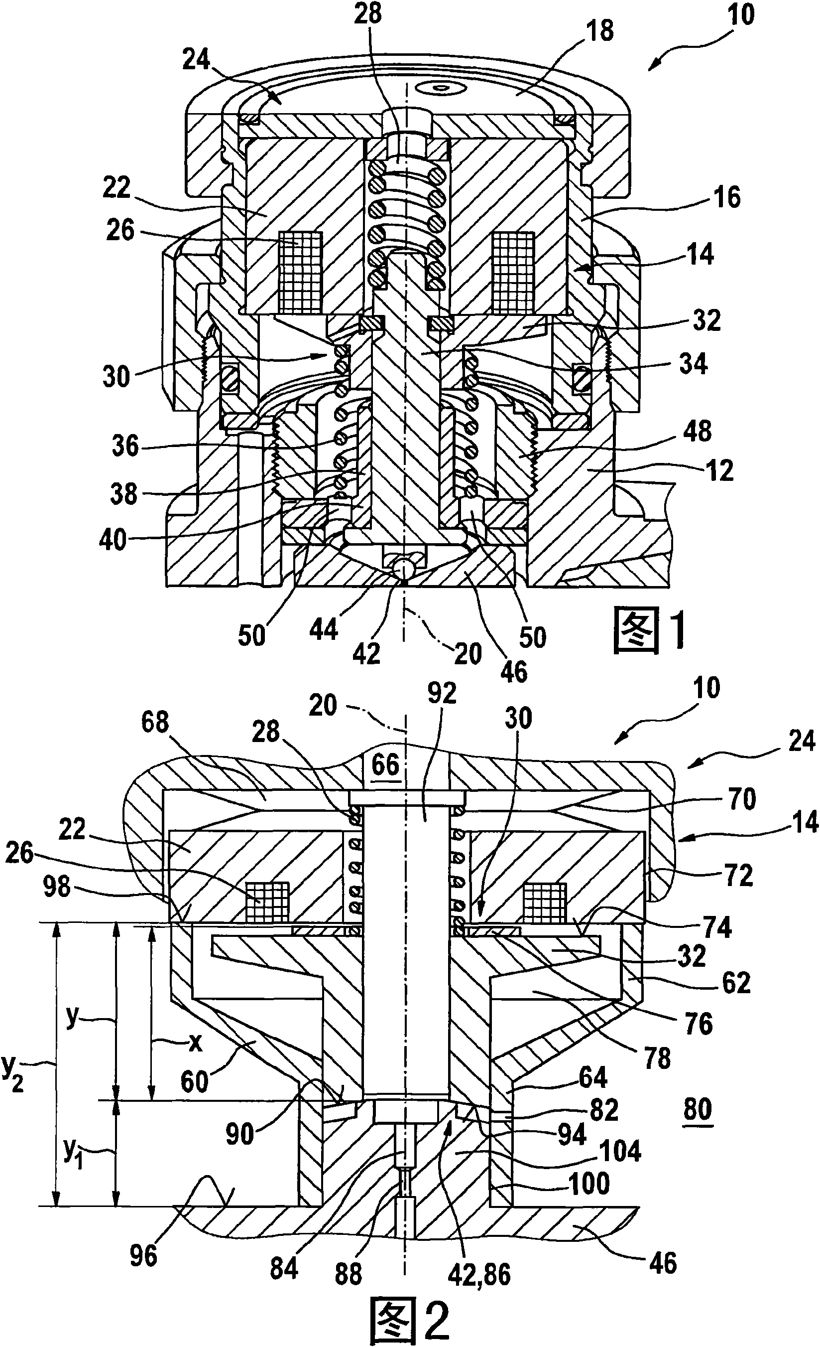
[0022] from according to figure 1 A solenoid valve according to the prior art is known from the diagram of FIG.

[0023] according to figure 1 The fuel injector 10 shown in the figure comprises a holding body 12 in which a solenoid valve 14 is received. The solenoid valve 14 is surrounded by a sleeve 16 which is closed by a cover 18 which can be fastened to the sleeve 16 with nuts or the like. according to figure 1 In the illustration in , the solenoid valve 14 is configured symmetrically with respect to the axis 20 .

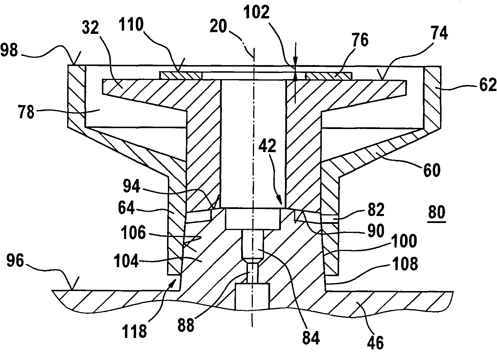
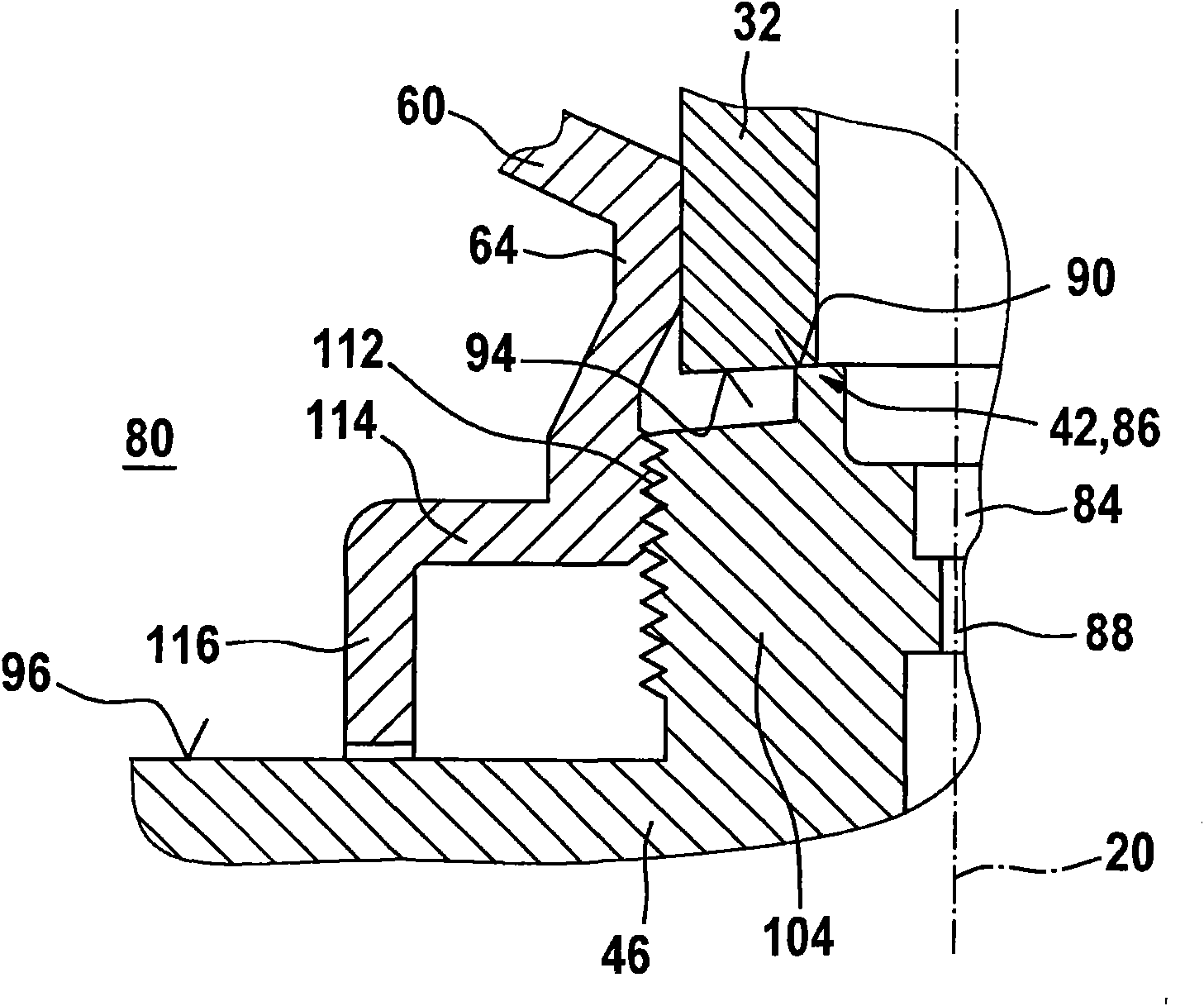
[0024] The solenoid valve 14 includes a magnetic core 22 that receives a return spring 28 . Furthermore, a solenoid coil 26 is embedded in the magnetic core 22 of the solenoid valve 14 . The armature plate 32 of the armature assembly 30 is opposite the lower end side of the magnetic core 22 . The armature plate 32 of the armature assembly 30 is loaded by the return spring 28 . from according to figure 1 It can also be seen from the diagram that, accordi...


PUM


Abstract

Fuel injector (10) having a holding body (12), into which a solenoid valve (14) is let which actuates an injection valve element of preferably needle-shaped configuration and has an armature assembly(30) which has an armature plate (32) and an armature stroke stop (40), and a sealing seat (42) is opened or closed by the armature assembly (30). A magnetic core (22) of the solenoid valve (14) is supported on a guide sleeve (60, 62, 64) which for its part is received on the valve element (46) such that it encloses a sealing seat (42, 86).

Description

Background technique [0001] DE 196 50 865 A1 discloses a solenoid valve for controlling the fuel pressure in a control chamber of an injection valve, for example for a common rail injection system. The stroke movement of the valve piston, which opens or closes the injection openings of the injection valve, is controlled by the fuel pressure in the control chamber. The solenoid valve includes an electromagnet, a movable armature and a valve, which can move together with the armature and is loaded in the closing direction by the valve return spring, which cooperates with the valve seat of the solenoid valve, whereby the control comes from the control chamber fuel drain. [0002] In today's leak-free designed fuel injectors actuated by means of solenoid valves, the coupling between the valve piston and the needle-shaped injection valve element takes place via a hydraulic coupling. The hydraulic coupling includes a coupling sleeve with an inner bore in which a valve piston is gu...

Claims


Application Information

Patent Timeline
Patent Type & Authority Applications(China)
IPC IPC(8): F02M47/02F02M59/46F02M61/16F02M63/00
CPCF02M2200/8092F02M63/0015F02M47/027F02M63/0075F02M63/004F02M63/0042F02M63/0077F02M63/0007F02M63/0043F02M2200/9076F02M61/168F02M63/0071F02M63/008
Inventor H·拉普
Owner ROBERT BOSCH GMBH
Why Eureka
Try Eureka