Resonance tension reducing sprocket with combined radial variation and sprocket wrap

A sprocket and tension technology, applied in the direction of elements with teeth, belt/chain/gear, hoisting device, etc., can solve the problems of increased wear and tear of the chain and sprocket system, etc.

Active Publication Date: 2010-03-24
BORGWARNER INC
View PDF2 Cites 0 Cited by
  • Summary
  • Abstract
  • Description
  • Claims
  • Application Information

AI Technical Summary

Problems solved by technology

As a result, a chain and sprocket system subjected to such tensions will typically suffer from greater wear and increased likelihood of failure, among other adverse effects, due to the concentration of these tensions in the lower stages

Method used


Image

  • Resonance tension reducing sprocket with combined radial variation and sprocket wrap
  • Resonance tension reducing sprocket with combined radial variation and sprocket wrap
  • Resonance tension reducing sprocket with combined radial variation and sprocket wrap

Examples


Embodiment Construction

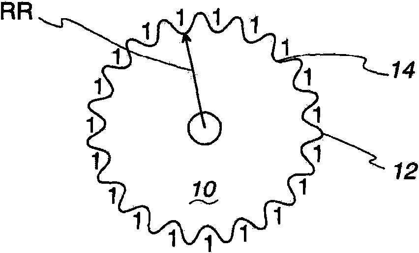
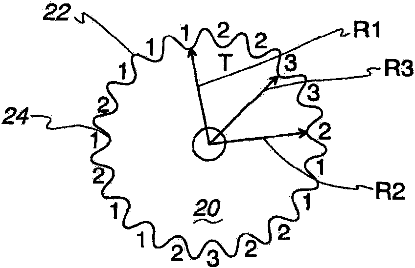
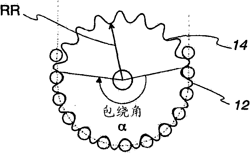
[0041] In the chain and sprocket system described herein, the effectiveness of the chain and sprockets in reducing chain tension is dependent on the radial variation or number of sprocket stages, the amount and angle the chain wraps around the sprockets, and the pitch circle or A combination of repeating sequences of root radii. The most efficient magnitude of the wrap angle is defined by Equation 1 given below:

[0042]

[0043] Among them: N=1, 2, ..., series -1

[0044] And, number of stages = number of sprocket stages caused by tensioning events originating outside the chain and / or sprockets.

[0045] In an important aspect of using the wrap angles described above, a random sprocket can be used in an automotive chain and sprocket system, such as in an engine timing system. The chain and sprockets are connected to an internal combustion engine which runs the chain and sprockets at variable speeds. The sprocket has a repeating sequence of dedendum or pitch radii connec...


PUM


Abstract

In a chain and sprocket assembly, the order of the sprocket and the wrap angle of the chain are selected such that the resonance tension of the chain and sprocket assembly is minimized.

Description

technical field [0001] The invention relates to the field of pulleys and sprockets. More specifically, the present invention relates to a chain and sprocket for reducing resonance tension. Background technique [0002] Chain and sprocket systems are often used in automotive engine systems to transmit rotational force between multiple shafts. For example, a sprocket on the driven shaft can be connected by a chain to a sprocket on the idler shaft. In such a chain and sprocket system, rotation of the driven shaft and driven sprocket will cause rotation of the idler shaft and idler sprocket through the chain. In an automotive engine system, multiple sprockets on the crankshaft can be used to drive one or more camshaft sprockets. [0003] These chains used in chain and sprocket systems typically include multiple link plates connected to pins or rollers, or they have multiple chains with meshing teeth connected to pins and / or links plate. These sprockets typically include a c...

Claims


Application Information

Patent Timeline
Patent Type & Authority Applications(China)
IPC IPC(8): F16H55/14F16H55/30
CPCF16H55/14F16H2055/306F16H55/30F16H2057/0087
Inventor K·B·托德
Owner BORGWARNER INC
Why Eureka
Try Eureka