Method for separating a mixture of carbon monoxide, methane, hydrogen, and optionally nitrogen by cryogenic distillation

A carbon monoxide and mixture technology, applied in the directions of carbon monoxide, cold treatment separation, liquefaction, etc., can solve the problems of inability to cool, low evaporation temperature, etc., and achieve the effect of saving energy, cost/investment

Active Publication Date: 2010-03-24
LAIR LIQUIDE SA POUR LETUDE & LEXPLOITATION DES PROCEDES GEORGES CLAUDE
View PDF2 Cites 13 Cited by
  • Summary
  • Abstract
  • Description
  • Claims
  • Application Information

AI Technical Summary

Problems solved by technology

At this pressure level, the evaporation temperature of CO is too low to cool the feed gas at the inlet of the methane scrubber: risk of methane freezing / freezing

Method used


Image

  • Method for separating a mixture of carbon monoxide, methane, hydrogen, and optionally nitrogen by cryogenic distillation
  • Method for separating a mixture of carbon monoxide, methane, hydrogen, and optionally nitrogen by cryogenic distillation
  • Method for separating a mixture of carbon monoxide, methane, hydrogen, and optionally nitrogen by cryogenic distillation

Examples


Embodiment Construction

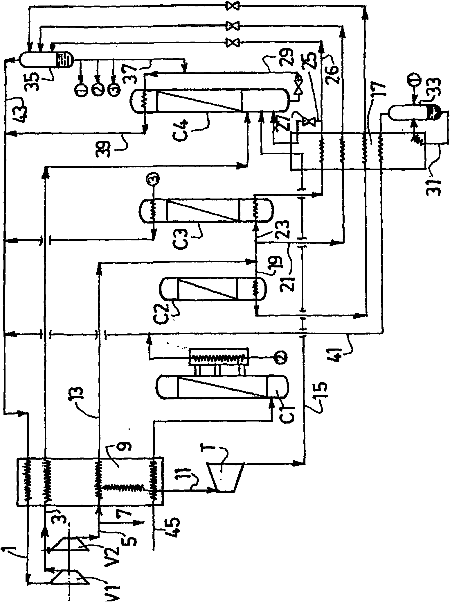
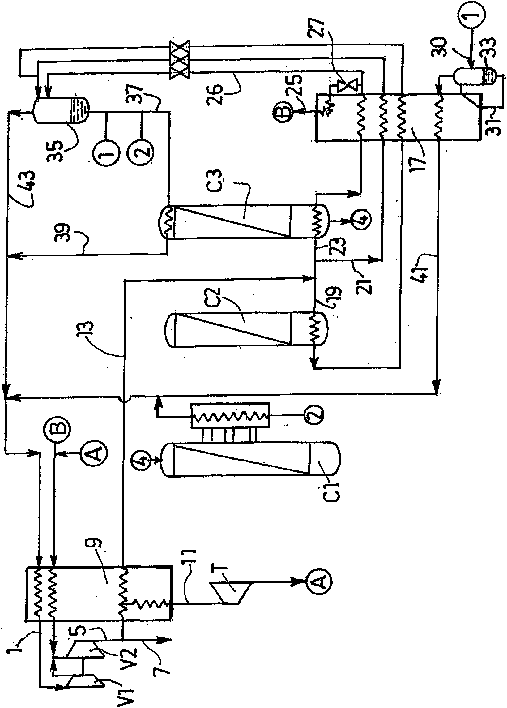
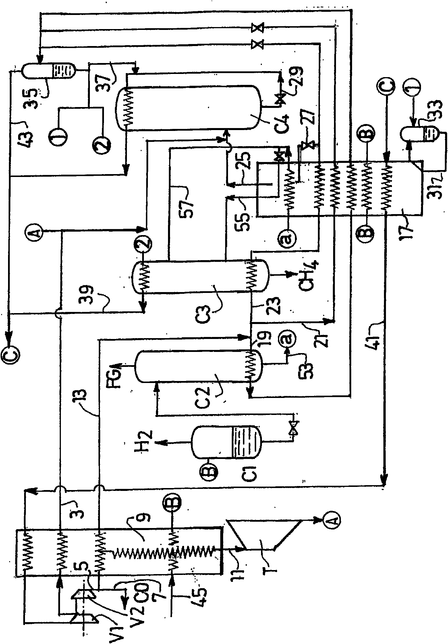
[0067] To simplify the attached figure 1 , only the inlet for the gas to be treated and the carbon monoxide cycle are shown.

[0068] Stream 45 comprising carbon monoxide, hydrogen, methane and nitrogen is cooled in exchanger 9 by heat exchange with carbon monoxide stream 1 and is sent to methane scrubber C1 which is fed at the top with very low temperature liquid methane stream.

[0069] However, it should be understood (although not shown) that liquid from the bottom of column C1 is sent to the top of stripping column C2. The hydrogen-rich gas from the top of column C1 leaves the plant. Liquid from the bottom of stripper C2 is sent to CO / CH 4 Separation column C3. Liquid from the bottom of column C3 is sent back to the top of column C1. Gas from the top of column C3 is sent to an intermediate position in denitrogenation column C4 where it is separated into a carbon monoxide-rich bottom liquid and nitrogen-rich overhead gas. The column arrangement is thus consistent wit...


PUM


Abstract

The invention relates to a method for separating a mixture comprising at least carbon monoxide, hydrogen, and methane. According to said method, the mixture is separated by a first separating means (C1), at least one liquid fraction of the chamber of the separating means is sent to a product stripper (C2), and at least part of the liquid fraction is sent from the product stripper to a CO / CH4 separating column (C3) in order to produce a methane-enriched liquid flow and a gaseous flow enriched with carbon monoxide. The process is carried out under cold conditions at least partially as a result of a carbon monoxide cycle, said cycle at least partially ensuring the condensation at the top of the CO / CH4separating column and / or the reboiling in the chamber of the product stripper and / or the reboiling in the chamber of the CO / CH4 separating column and / or the cooling of the mixture for the first separating means.

Description

technical field [0001] The present invention relates to a method for separating a mixture comprising carbon monoxide, methane, hydrogen and optionally nitrogen by cryogenic distillation. Background technique [0002] known in Linde Reports on Science and Technology, “Progress in H 2 / COLow-Temperature Separation", Berninger, 44 / 1988 and "A New Generation of Cryogenic H 2 / CO Separation Processes Successfully in Operation at Two Different Antwerp Sites", Belloni, International Symposium on Gas Separation Technology, 1989, describes the separation of this mixture by a methane scrubbing / scrubbing process for the production of carbon monoxide and hydrogen. [0003] Other documents describing methane scrubbing processes include: EP-A-0928937, US4478621 and Tieftemperaturtechnik, p.418. [0004] from h 2 The carbon monoxide obtained in the / CO cold box entrains a large part of the nitrogen in the feed gas. This phenomenon and the two components CO and N 2 It is difficult to s...

Claims


Application Information

Patent Timeline
Patent Type & Authority Applications(China)
IPC IPC(8): F25J3/02C01B32/40
CPCF25J2205/04F25J2200/70F25J2200/74F25J2270/08F25J3/0252F25J3/0223F25J2205/30F25J2270/04F25J2270/02F25J3/0233F25J2270/24F25J3/0261F25J3/0257F25J2200/40Y10S62/92
Inventor A·达德N·艾克-贝劳德A·埃尔南德斯G·特谢拉
Owner LAIR LIQUIDE SA POUR LETUDE & LEXPLOITATION DES PROCEDES GEORGES CLAUDE
Why Eureka
Try Eureka