
Laminate and solar battery using the laminate

A technology of solar cells and laminates, applied in the field of dye-sensitized solar cells, which can solve the problems of expensive microwave irradiation devices, easy deterioration of resin substrates, and difficulty in manufacturing batteries, and achieve good long-term stability, safety and durability , the effect of improving manufacturing efficiency

Inactive Publication Date: 2010-03-24
NIPPON ELECTRIC GLASS CO LTD
View PDF6 Cites 6 Cited by
  • Summary
  • Abstract
  • Description
  • Claims
  • Application Information

AI Technical Summary

Problems solved by technology

However, when a solar cell using a resin substrate is used outdoors, the resin substrate is easily degraded by ultraviolet rays, etc., or because the resin has high air permeability, the enclosed matter (electrolyte solution components) in the battery volatilizes through the resin. aspects, it is difficult to manufacture practical batteries
In addition, there is a disadvantage that the microwave irradiation device is expensive and difficult to apply in industry

Method used


Image

  • Laminate and solar battery using the laminate
  • Laminate and solar battery using the laminate
  • Laminate and solar battery using the laminate

Examples


Embodiment

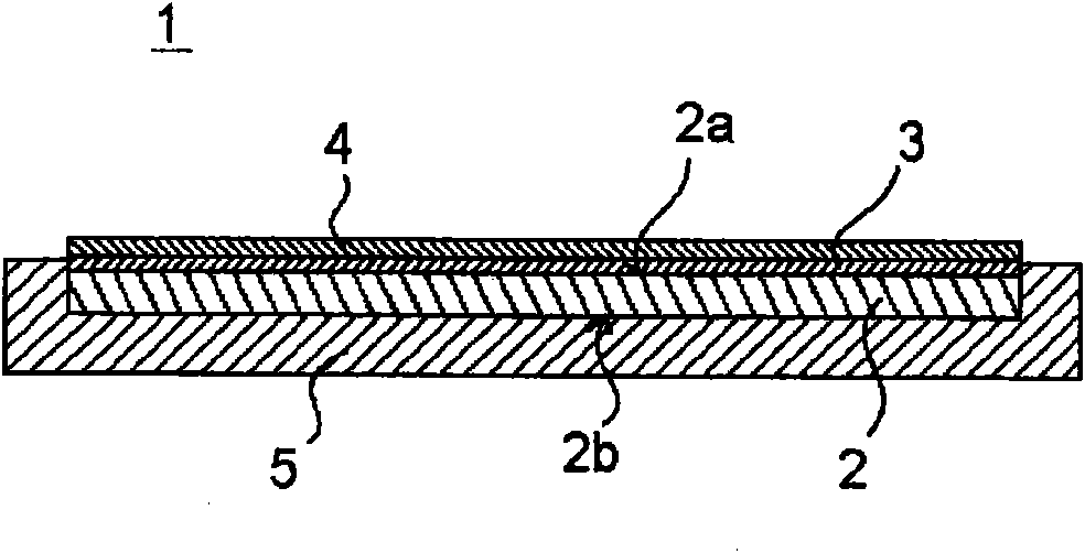
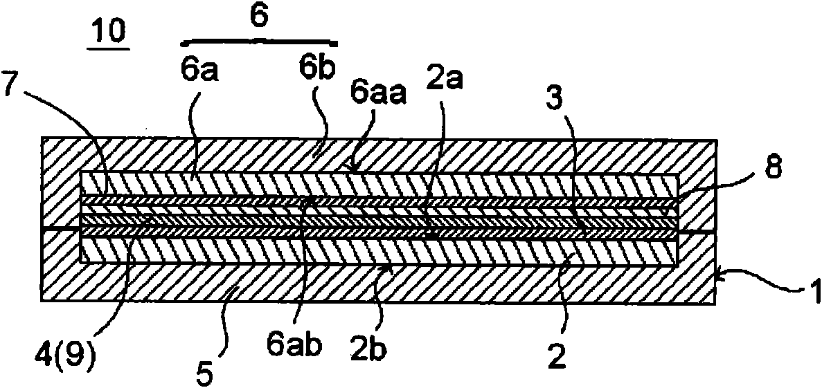
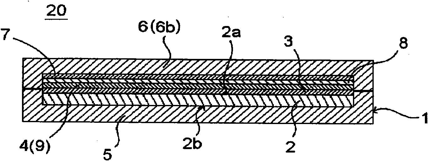
[0059] Next, embodiments of the present invention will be described based on the drawings and tables. figure 1 It is an explanatory drawing of the laminated body of this invention, figure 2 It is an explanatory diagram of the dye-sensitized solar cell of the present invention. image 3 It is an explanatory diagram of another dye-sensitized solar cell of the present invention. Table 1 shows Examples 1-5 of the present invention, Table 2 shows Examples 6-8, Table 3 shows Examples 9-12, and Table 4 shows Comparative Examples 1-3.

[0060] Table 1

[0061]

[0062] Table 2

[0063]

[0064] table 3

[0065]

[0066] Table 4

[0067]

[0068] Such as figure 1 As shown, the laminated body 1 of Examples 1 to 5 and Comparative Examples 1 and 2 includes a first glass plate 2 having a first surface 2 a and a second surface 2 b, and a conductive material formed on the first surface 2 a of the first glass plate 2 . The film 3 , the photoactive layer 4 formed on the con...


PUM

PropertyMeasurementUnit
strain pointaaaaaaaaaa
thicknessaaaaaaaaaa
thicknessaaaaaaaaaa

Abstract

This invention provides a light-weight laminate, which can withstand heat treatment in a battery production process and, at the same time, has practically satisfactory durability, and a solar battery using the laminate. The laminate comprises a glass plate having a first surface and a second surface, an electroconductive film provided on the first surface of the glass plate, and a photoactive layer provided on the electroconductive film. The laminate is characterized in that the glass plate is formed of a glass having a distortion point of 400 DEG C or above and a thickness of 10 mu m to 2.2 mm, and a resin is provided on the second surface of the glass plate. The solar battery is characterized in that it comprises: a laminate comprising a glass plate having a first surface and a second surface, an electroconductive film provided on the first surface of the glass plate, and a photoactive layer provided on the electroconductive film; a light transparent base material; a transparent electrode provided on one side of the light transparent base material; and an electrolysis solution sealed between the laminate and the transparent electrode, the glass plate is formed of a glass having a distortion point of 400 DEG C or above and a thickness of 10 mu m to 2.2 mm, and a resin is provided on the second surface of the glass plate.

Description

technical field [0001] The present invention relates to a stacked body, especially a stacked body for a solar cell and a solar cell using the stacked body, especially a dye-sensitized solar cell. Background technique [0002] Now, solar cells are attracting attention as the second generation of clean energy. Among them, dye-sensitized solar cells have been attracting attention in recent years because they are easy to manufacture, have a small environmental load for manufacturing the cells, and have good indoor power generation efficiency. At present, solar cells use a structure in which power generation materials are placed on a glass substrate, but the glass substrate is heavy or the device cannot be made into a curved shape, which poses constraints in construction. [0003] In addition, in this technical field, the development of lightweight and flexible solar cells is particularly required. In addition, the light source used for solar cell power generation does not nece...

Claims


Application Information

Patent Timeline
Patent Type & Authority Applications(China)
IPC IPC(8): H01M14/00B32B17/10H01B5/14H01L31/04
CPCC03C2217/71H01G9/2059B32B17/10018C03C17/245C03C17/3417B32B17/10H01L31/022466B32B17/064H01G9/2095C03C17/3411H01L31/048B32B17/10174C03C2217/948B32B17/10036H01G9/2031B32B2327/12B32B2327/00Y02E10/542
Inventor 坂本明彦泽田正弘
Owner NIPPON ELECTRIC GLASS CO LTD
Learn More