Ball plunger for use in a hydraulic lash adjuster and method of making same
A gap adjuster and ball plunger technology, applied in the field of ball plungers, can solve the problems of increasing the cost and time consumption of finished ball plungers
- Summary
- Abstract
- Description
- Claims
- Application Information
AI Technical Summary
Problems solved by technology
Method used
Image
Examples
Embodiment Construction
[0016] The specific terms used in the above description for convenience are for reference only and not for limitation. The terms "upwardly", "downwardly", "upper" and "lower" are to be understood to have their standard meanings and refer to those directions when the drawings are normally viewed. All of the above terms mentioned above include normal derivatives and equivalents thereof.
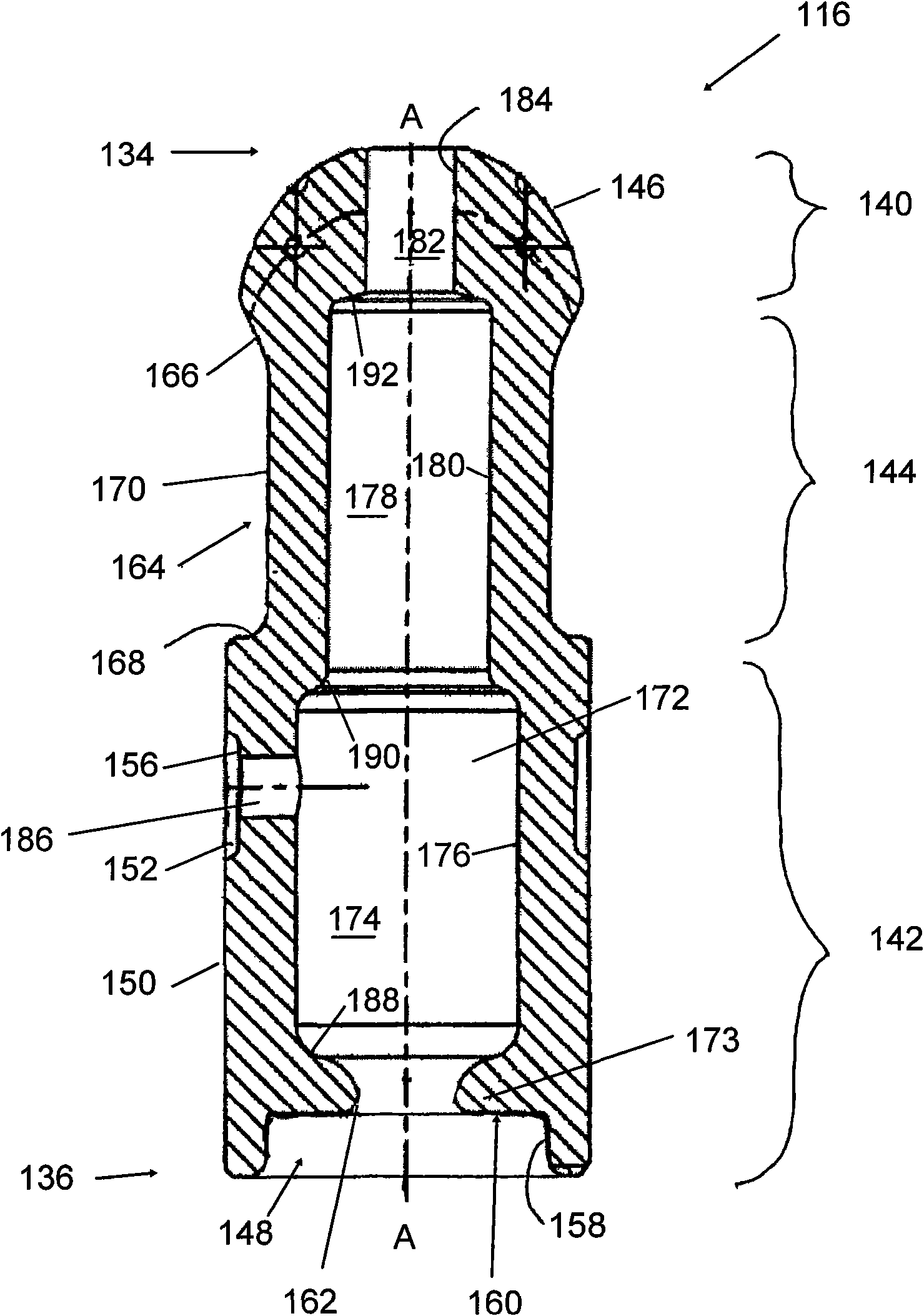
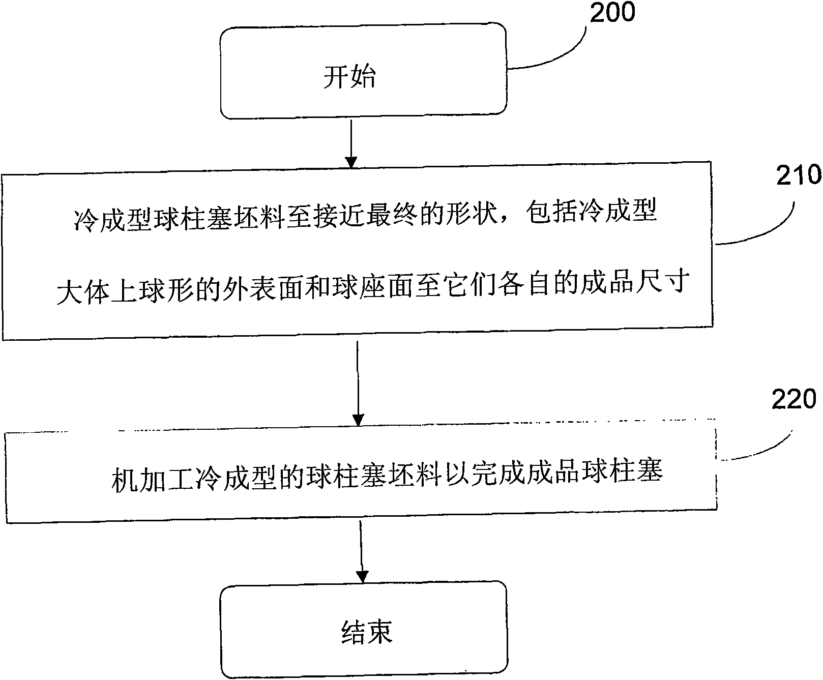
[0017] This application relates to ball plungers for use in hydraulic lash adjusters. The ball plunger is a one-piece structure that is cold formed to a near net shape, requiring less machining to complete the finished part than prior art ball plungers.
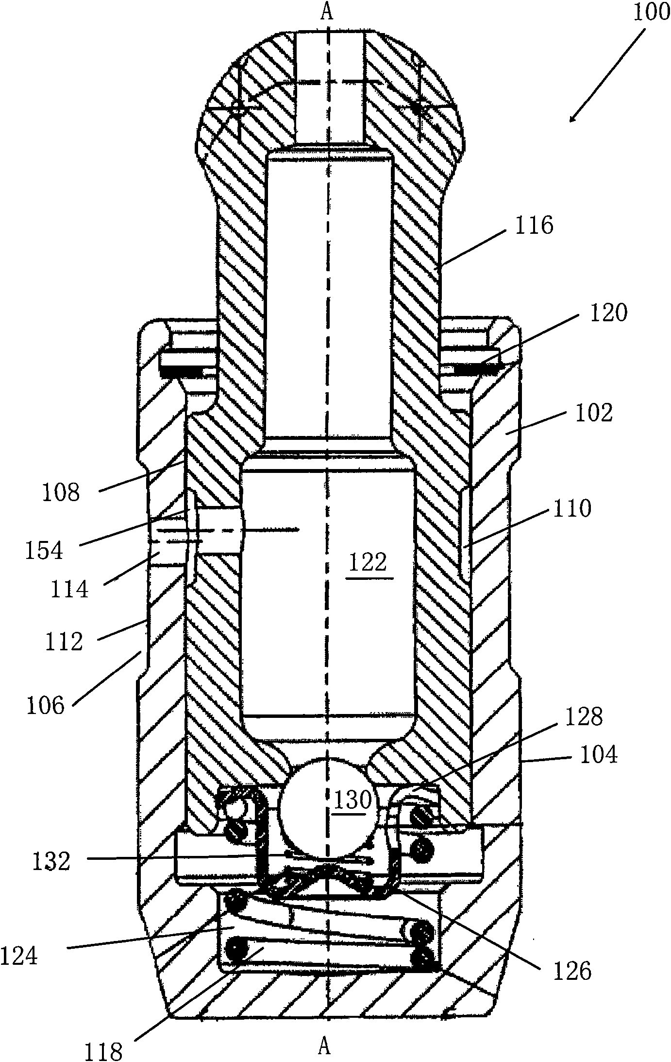
[0018] Figure 1A A cross-sectional view of an exemplary hydraulic lash adjuster 100 is shown. The hydraulic lash adjuster 100 is a variation of a Type II valve train and is shown by way of example only, and it will be understood that the ball plunger employed therein may be used in any hydraulic lash adjuster configuration and is not limiti...
PUM
 Abstract
Description
Claims
Application Information
 - R&D
- Intellectual Property
- Life Sciences
- Materials
- Tech Scout
- Unparalleled Data Quality
- Higher Quality Content
- 60% Fewer Hallucinations
Browse by: Latest US Patents, China's latest patents, Technical Efficacy Thesaurus, Application Domain, Technology Topic, Popular Technical Reports.
© 2025 PatSnap. All rights reserved.Legal|Privacy policy|Modern Slavery Act Transparency Statement|Sitemap|About US| Contact US: help@patsnap.com


