
Method for realizing downstream data beam formation and system thereof

A technology of beamforming and implementation method, applied in baseband system components, shaping network in transmitter/receiver, advanced technology, etc. Inconsistency, upward and downward angle deviation, etc.

Inactive Publication Date: 2010-03-31
ZTE CORP
View PDF0 Cites 28 Cited by
  • Summary
  • Abstract
  • Description
  • Claims
  • Application Information

AI Technical Summary

Problems solved by technology

[0003] The downlink beamforming algorithm based on uplink DOA estimation is to use the reciprocity of the uplink and downlink channels in the time division duplex mode to complete the downlink beamforming. The problem with this method is that the uplink and downlink beams corresponding to the antenna array Inconsistencies in channel characteristics, there must be a certain degree of difference in the amplitude-frequency characteristics and phase-frequency characteristics of each channel, resulting in deviations in the uplink and downlink angles
[0005] In the prior art, the interference between uplink and downlink is not completely reciprocal, and the interference from other base stations seen in the downlink mobile terminal, rather than the interference from other mobile terminals, determines the weight in the downlink Therefore, the downlink interference suppression is not equally effective for the uplink; on the other hand, when the uplink DOA estimation results are used for downlink beamforming, the antenna array corresponds to the inconsistency of the uplink and downlink channel characteristics. There must be a certain degree of difference in the amplitude-frequency characteristics and phase-frequency characteristics of each channel, resulting in deviations in the uplink and downlink angles.

Method used


Image

  • Method for realizing downstream data beam formation and system thereof
  • Method for realizing downstream data beam formation and system thereof
  • Method for realizing downstream data beam formation and system thereof

Examples


Embodiment Construction

[0033] Various preferred embodiments of the present invention will be described in detail below in conjunction with the accompanying drawings.

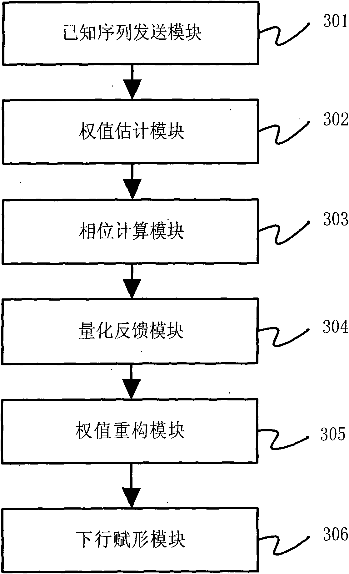
[0034] A downlink beamforming method based on feedback information provided by the present invention uses the terminal to calculate weights and feeds them back to the base station through a feedback channel, and finally the base station uses the weights to complete beamforming of downlink data , which reduces the array error and improves the reliability of the system. Method of the present invention comprises the following steps:

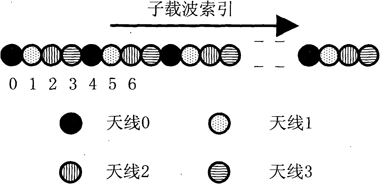
[0035] Step a: The base station periodically sends the downlink known sequence to the terminal in the pre-allocated time-frequency resource area. The known sequence is a training sequence, and its format is as follows figure 1 shown;

[0036] Step b: The terminal performs weight estimation according to the received known sequence;

[0037] Step c: the terminal extracts corresponding phase information acc...


PUM


Abstract

The invention discloses a method for realizing downstream data beam formation and a system thereof; the method comprises: a base station transmits a downstream known sequence periodically to a terminal in a pre-distributive time-frequency resource section; the terminal carries out weight value estimation and extracts the corresponding phase information according to the received known sequence; theterminal carries out quantification to the corresponding phase and feeds back the quantified feedback bit to the base station by an upstream feedback channel; the base station reconstructs a weight vector according to the received feedback bit, and beam formation is carried out to the downstream data according to the feedback channel, the base station utilizes the weight value to carry out downstream data beam formation, so as to lead the system to trace the change condition of a user timely, achieve better beam trace effect, reduce array error, improve the reliability of the system, expand signal coverage range and reduce sending power.

Description

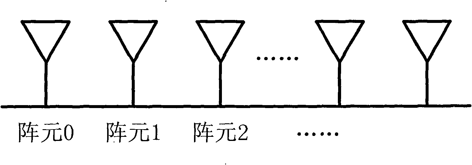
technical field [0001] The invention relates to the field of wireless communication, in particular to a downlink beamforming method and system thereof using a uniform linear array smart antenna in an OFDMA communication system. Background technique [0002] A smart antenna is a device that uses an antenna array to combine and direct beams. It can adaptively adjust its pattern to track signal changes. It uses digital signal processing technology to generate spatially directional beams and align the main beam of the antenna. The direction of arrival of the user signal, the sidelobe or null point is aligned with the direction of arrival of the interference signal, so as to fully and efficiently use the useful signal of the mobile user and suppress or delete the interference signal, thereby improving the system capacity, expanding the coverage, and improving the communication efficiency. Reliability, reduced transmit power and reduced operating costs. Downlink beamforming algor...

Claims


Application Information

Patent Timeline
IPC IPC(8): H04W16/28H04L25/02H04L25/03
CPCY02B60/50Y02D30/70
Inventor 李远英王雯芳李玉洁刘巧艳赵路
Owner ZTE CORP
Learn More