Multi-wire saw and method of cutting ingot

A wire saw and billet technology, which is applied in the field of multi-wire saw and billet cutting, can solve the problems of shallow guide grooves, broken wires, defects, etc., and achieve the effect of reducing plate thickness deviation and improving the yield

Inactive Publication Date: 2010-03-31
MITSUBISHI ELECTRIC CORP
View PDF1 Cites 5 Cited by
  • Summary
  • Abstract
  • Description
  • Claims
  • Application Information

AI Technical Summary

Problems solved by technology

For this reason, if the thickness of the wafer end is thin, it cannot withstand the repeated pressing force, and cracks or defects will occur at the wafer end, which will become a defective product.
[0005] In addition, in order to thin the wafer, the distance between the wires must be reduced, but the guide groove formed in the wire guide roller becomes shallow accordingly, and the probability of the wire falling out of the guide groove becomes high.
When the wire is detached from the guide groove, either the wafers around it cannot be cut, or in the worst case, the wire is entangled and the wire breaks, and no qualified wafer can be obtained.
[0006] Such a problem of displacement or detachment of the wire from the guide groove of the wire guide roller is significant after the silicon ingot is cut.

Method used


Image

  • Multi-wire saw and method of cutting ingot
  • Multi-wire saw and method of cutting ingot
  • Multi-wire saw and method of cutting ingot

Examples


Embodiment approach 1

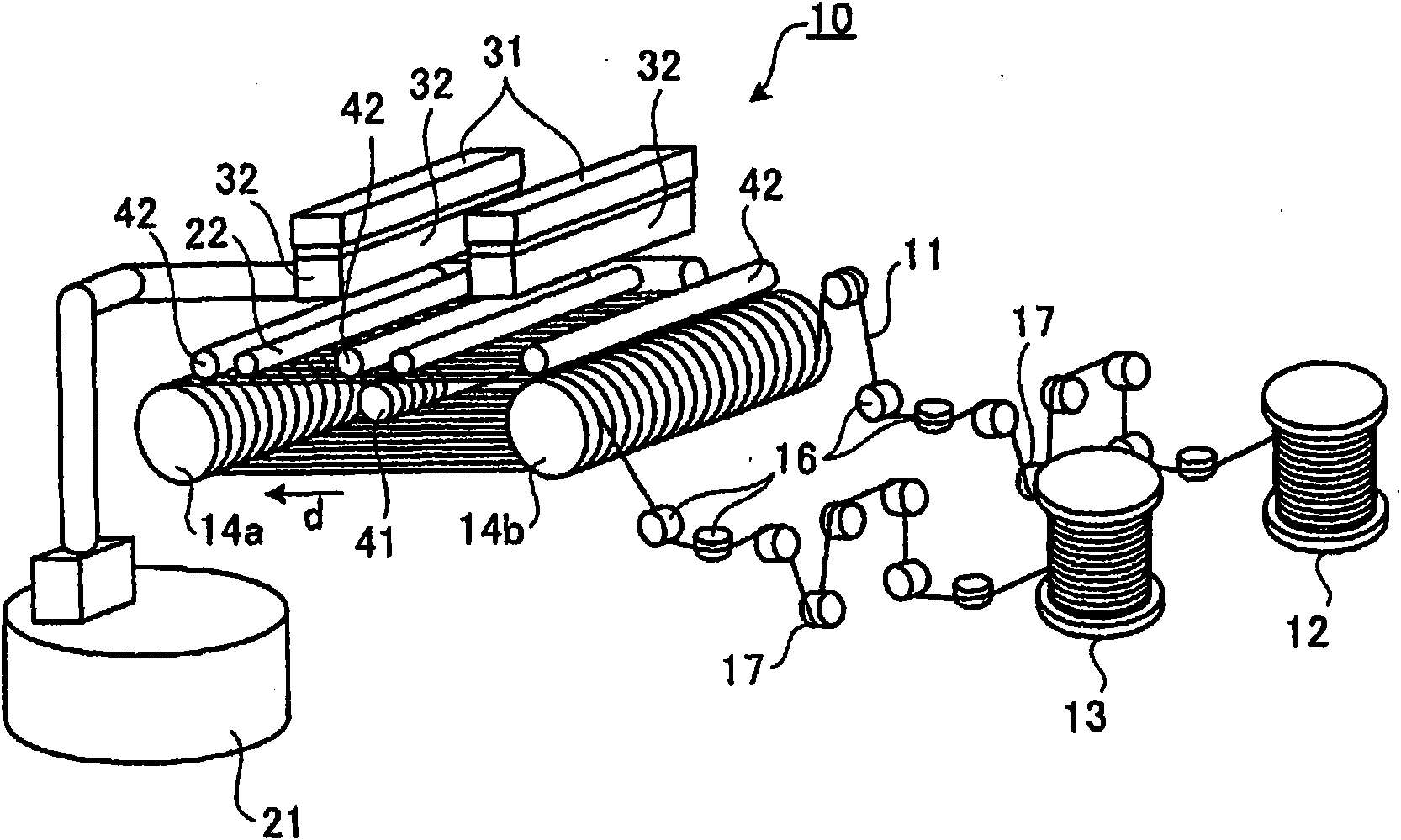
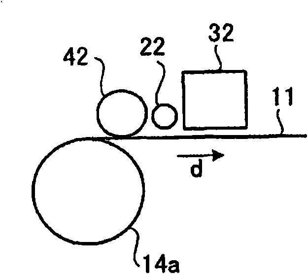
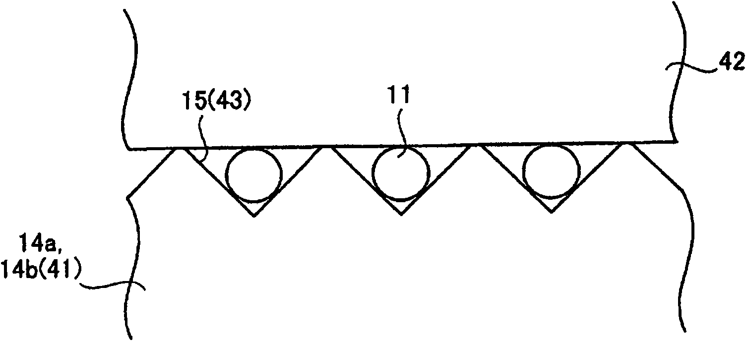
[0031] figure 1 It is a perspective view showing the structure of the main part of the multi-wire saw of the present invention, figure 2 It is a side view of the structure near the wire guide roller viewed from the direction of the wire guide roller rotation axis, image 3 It is a figure which schematically shows the relationship of a wire regulation part and a wire guide roller.

[0032] Such as figure 1 As shown, the multi-wire saw 10 has: a wire 11; a wire sending mechanism 12 for sending out the wire 11; a wire winding mechanism 13 for winding the sent wire 11; Between the two wire guide rollers 14a, 14b arranged in a manner that the rotation axes are parallel to each other; between the wire feeding mechanism 12 to the wire guide roller 14a and from the wire guide roller 14b to the wire winding mechanism 13 a plurality of guide rollers 16 that each guide the wire 11 to travel; and a tension roller 17 that controls the tension of the wire 11 guided by the guide rollers ...

Embodiment approach 2

[0041] Figure 4 It is a block diagram showing the functional configuration of the control unit of the multi-wire saw according to the present invention. This control unit 50 has a wire deflection profile calculation unit 51 and a processing control unit 52 . In addition, the configuration of the multi-wire saw 10 controlled by the control unit 50 is the same as that in the first embodiment. figure 1 The shown configurations are the same, so descriptions thereof will be omitted.

[0042] The wire deflection profile calculation unit 51 derives the deflection of the wire 11 at a predetermined cutting position when the depth of the cutting groove formed when cutting the blank 32 is started is at least equal to or deeper than the radius of the wire 11 . Figure 5 It is a cross-sectional view schematically showing the state in which the blank is cut to a depth e when the blank is started to be cut, Figure 6 It is a diagram schematically showing the state of the multi-wire saw v...

Embodiment approach 3

[0052] In the above-mentioned Embodiments 1 and 2, the wire lifting restricting member 42 that prevents the wire 11 from floating can also be made into a cylindrical shape of revolution, that is, it is provided on the cylindrical surface and formed on the wire. The guide grooves 15, 43 of the guide rollers 14a, 14b, 41 are equally spaced grooves.

[0053] According to this Embodiment 3, by forming the guide groove on the surface of the wire lifting restricting member 42, compared with the case of the cylindrical revolving body which is not formed at all, it is possible to further suppress the lateral movement of the wire at the moment of cutting start. Pendulum, the effect of further reducing the plate thickness deviation at the edge of the wafer.

[0054] Hereinafter, effects when cutting a material with the multi-wire saw 10 according to Embodiments 1 to 3 described above will be described. Cutting experiments were performed three times each using the multi-wire saw 10 havi...


PUM

PropertyMeasurementUnit
diameteraaaaaaaaaa
lengthaaaaaaaaaa
diameteraaaaaaaaaa

Abstract

Provided is a multi-wire saw that can prevent wires from being displaced in guide roller grooves due to the lifting of the wires when the cutting of an ingot is started. Wires (11) are wound around wire guide rollers (14a, 14b, 41), and positioned in the feeding direction of an ingot (32). In such a state, restraining members (42) comprising rotary bodies which are brought into contact with the wires (11), thereby restraining the lifting of the wires are disposed near the wire guide rollers (14a, 14b, 41).

Description

technical field [0001] The present invention relates to a multi-wire saw and a blank cutting method for blank cutting for manufacturing wafers. Background technique [0002] Conventionally, in order to cut a silicon ingot, a multi-wire saw capable of cutting a plurality of wafers at one time with a relatively small cutting amount is used. Such a multi-wire saw is configured such that the wire fed out by the wire feeding mechanism is wound between two wire guide rollers at a pitch of about 0.3 to 0.4 mm, and the wire is wound by the wire winding mechanism. In addition, between the wire feeding mechanism and the wire guide roller, and between the wire guide roller and the wire winding mechanism, there are provided tension rollers that constantly apply a predetermined tension to the wire. In the multi-wire saw constituted in this way, the wire feeding mechanism, the two wire guide rollers and the wire winding mechanism are driven synchronously, and the position of the tension ...

Claims


Application Information

Patent Timeline
Patent Type & Authority Applications(China)
IPC IPC(8): B24B27/06B28D5/04H01L21/304
CPCB23D57/0023B23D57/0061B28D5/045B24B27/0633
Inventor 河崎贵文三村诚一西田博一
Owner MITSUBISHI ELECTRIC CORP
Why Eureka
Try Eureka