Low ripple wave boosting type charge pump

A charge pump and boost technology, applied in the field of low ripple boost charge pump, can solve the problem of large ripple of the charge pump and achieve the effect of low ripple

Inactive Publication Date: 2010-04-14
IPGOAL MICROELECTRONICS (SICHUAN) CO LTD
View PDF0 Cites 24 Cited by
  • Summary
  • Abstract
  • Description
  • Claims
  • Application Information

AI Technical Summary

Problems solved by technology

The feedback methods of the charge pump include discrete and continuous feedback methods. Compared with the

Method used


Image

  • Low ripple wave boosting type charge pump
  • Low ripple wave boosting type charge pump
  • Low ripple wave boosting type charge pump

Examples


Embodiment Construction

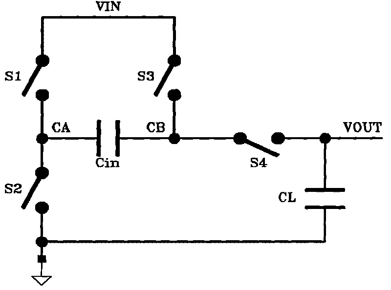
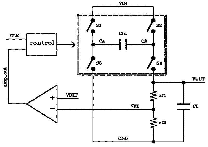
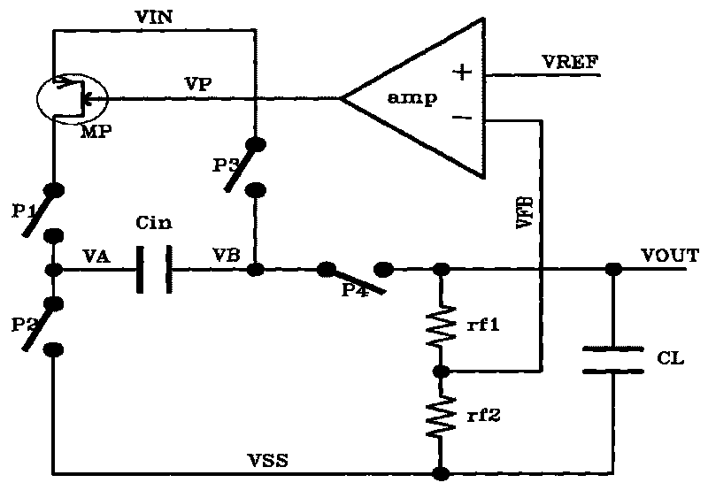
[0041] The low-ripple boost charge pump includes a single-capacitor doubler circuit, and a continuous feedback circuit is provided between the output voltage VOUT and the input voltage VIN of the single-capacitor doubler circuit, and the continuous feedback circuit includes sequentially connected Output voltage sampling branch, operational amplifier and adjustment tube; the output voltage sampling branch is used to detect the output voltage, and the detected voltage VFB is input to one input terminal of the operational amplifier, and the other input terminal of the operational amplifier is the reference voltage VREF , the output terminal of the operational amplifier is connected to the input terminal of the pass tube;

[0042] The change of the output voltage VFB controls the output of the operational amplifier, and the voltage loss at the input end and the output end of the adjustment tube is the same as the change of the output voltage VFB;

[0043] The sum of the total volt...


PUM


Abstract

The invention discloses a low ripple wave boosting type charge pump which comprises a single-capacitor voltage doubling circuit, wherein a continuous feedback circuit is arranged between the output voltage and the input voltage of the single-capacitor voltage doubling circuit; the continuous feedback circuit comprises an output voltage sampling branch circuit, an operation amplifier and an adjusting pipe which are sequentially connected; the detecting voltage and the reference voltage of the output voltage sampling branch circuit are respectively connected to both input ends of the operation amplifier, the output end of the operation amplifier is connected to the input end of the adjusting pipe, and a feedback mechanism of the continuous feedback circuit finally stabilizes the output voltage to a preset value. The continuous feedback mechanism comprising the output voltage sampling branch circuit, the operation amplifier and an active adjusting pipe is added; on one hand, when the factor of input voltage or temperature, and the like is changed, the stability of the output voltage is maintained by feedback; on the other hand, a ripple wave of the output voltage does not comprise the unideal factor of offset voltage, and the like due to the continuity of the feedback, thereby having a lower ripple wave.

Description

technical field [0001] The invention relates to the field of charge pumps, in particular to a low-ripple step-up charge pump. Background technique [0002] With the rapid development of integrated circuit manufacturing technology, in order to pursue low cost, the device size used in IC design is getting smaller and smaller, corresponding to the lower and lower power supply voltage. However, in many applications, a higher voltage than the power supply voltage is required, such as: LED integrated drive design, voltage sampling switch drive, etc. Current boost technologies include: AC-DC, DC-DC and charge pump. In applications where the boost amplitude and load requirements are not high, a charge pump is the preferred boost implementation. [0003] The traditional single-capacitor doubler charge pump structure such as figure 1 As shown, where Cin is the voltage doubler capacitor, which is externally connected to the chip during design. This capacitor is a "single capacitor" b...

Claims


Application Information

Patent Timeline
IPC IPC(8): H02M3/07
Inventor 叶飞
Owner IPGOAL MICROELECTRONICS (SICHUAN) CO LTD
Why Eureka
Try Eureka