Method for positioning mold core and mold shell of hollow blade

A technology of hollow blades and cores, applied in the direction of cores, molds, mold components, etc., can solve problems such as broken cores and eccentric cores, and achieve the effects of large economic benefits, uniform wall thickness, and shortened processing cycles

Active Publication Date: 2010-04-21
SHENYANG LIMING AERO-ENGINE GROUP CORPORATION
View PDF0 Cites 42 Cited by
  • Summary
  • Abstract
  • Description
  • Claims
  • Application Information

AI Technical Summary

Problems solved by technology

[0005] Aiming at the shortcomings of the above prior art, the present invention provides a hollow blade core and shell positioning method to improve the wall thickness and dimen

Method used


Image

  • Method for positioning mold core and mold shell of hollow blade
  • Method for positioning mold core and mold shell of hollow blade
  • Method for positioning mold core and mold shell of hollow blade

Examples


Embodiment 1

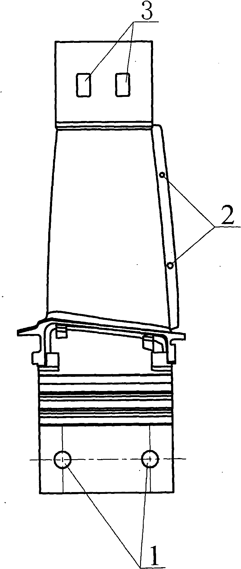
[0023] According to the temperature field distribution characteristics of the high-turbulence blade ceramic core and shell during the directional solidification process, as well as the analysis of physical characteristics such as the linear expansion of the core and the shell itself, the point and surface direct contact method is adopted for the positioning of the ceramic core.

[0024] The blade tip extension section is provided with a blade tip positioning point, and the blade tip extension section where the blade tip positioning point is located is used as a fixed end, which adopts a direct surface contact type; the exhaust side is coated with a free end, and two positioning points are made on the free end, here The core and the shell adopt the point contact type; the extension of the tenon tooth also adopts point positioning, and two tower positioning points are made on the tenon tooth extension section, and the point contact type is adopted; the positioning method of the co...

Embodiment 2

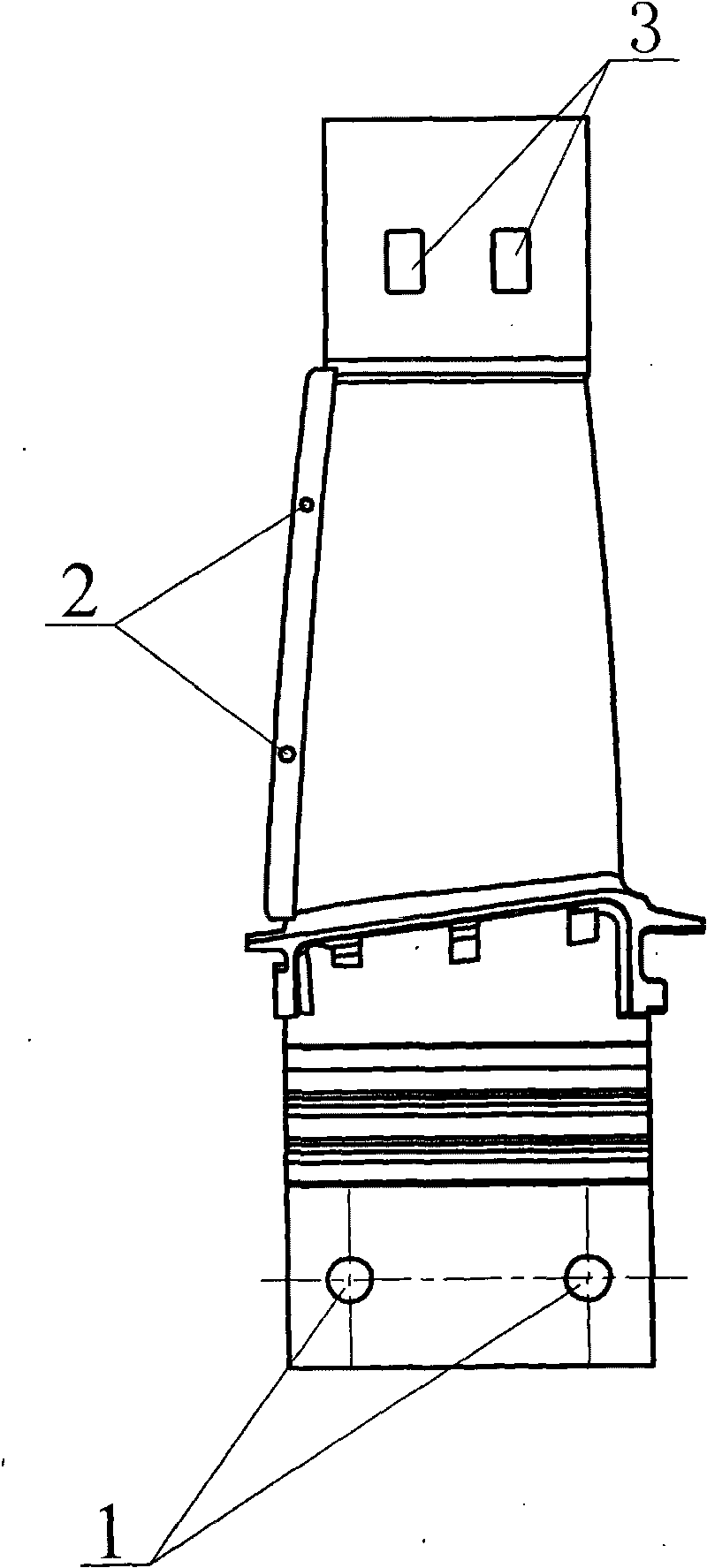
[0033] According to the temperature field distribution characteristics of the high-turbulence blade ceramic core and shell during the directional solidification process, as well as the analysis of physical characteristics such as the linear expansion of the core and the shell itself, the point and surface direct contact method is adopted for the positioning of the ceramic core.

[0034] The blade tip extension section is provided with a blade tip positioning point, and the blade tip extension section where the blade tip positioning point is located is used as a fixed end, which adopts a direct surface contact type; the exhaust side is coated with a free end, and two positioning points are made on the free end, here The core and the shell adopt the point contact type; the extension of the tenon tooth also adopts point positioning, and two tower positioning points are made on the tenon tooth extension section, and the point contact type is adopted; the positioning method of the co...

Embodiment 3

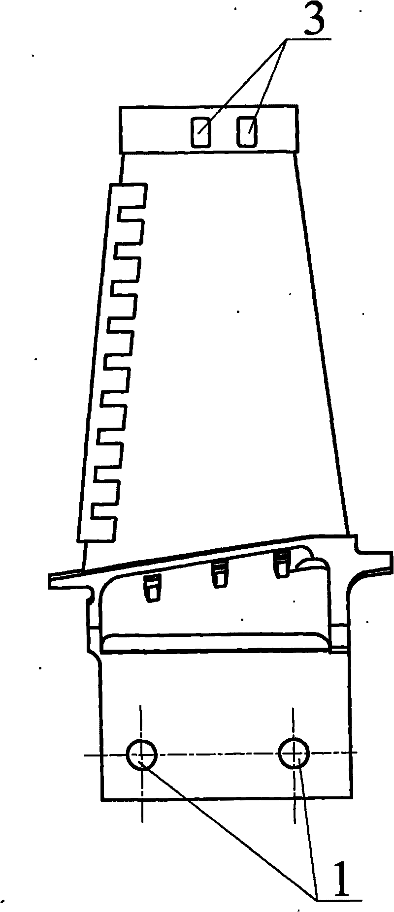
[0043] According to the temperature field distribution characteristics of the high-turbulence blade ceramic core and shell during the directional solidification process, as well as the analysis of physical characteristics such as the linear expansion of the core and the shell itself, the point and surface direct contact method is adopted for the positioning of the ceramic core.

[0044]The blade tip extension section is provided with a blade tip positioning point, and the blade tip extension section where the blade tip positioning point is located is used as a fixed end, which adopts a direct surface contact type; the exhaust side is coated with a free end, and two positioning points are made on the free end, here The core and the shell adopt the point contact type; the extension of the tenon tooth also adopts point positioning, and two tower positioning points are made on the tenon tooth extension section, and the point contact type is adopted; the positioning method of the cor...


PUM


Abstract

The invention discloses a method for positioning a mold core and a mold shell of a hollow blade, which belongs to the technical field of aero engines and combustion gas turbines. The expansion section of a blade tip is provided with a blade tip positioning point; the expansion section, wherein the blade tip positioning point is, of the blade tip serves as a fixed end and a surface direct contact is adopted; an exhaust side is coated with a free end, two positioning points are made on the free end, the mold core and the mold shell adopt point contact at the positions; an expansion section of tenon teeth also adopts point positioning; two tower type positioning points are made on the expansion section of the tenon teeth, and point direct contact is adopted; and a mold core blade basin and a blade back adopt the same positioning method and the positioning positions are symmetric. The method of the invention is a breakthrough of the traditional positioning method in the same industry in China and has the advantages that: operation in production is simple and convenient; the processing period of the blade casting is shortened; and the quality, qualification rate and production efficiency of the casting are improved. Production and test work proves that the blade casting produced by using the positioning method has the advantage that core deflection and breakage conditions are greatly reduced in a casting process.

Description

technical field [0001] The invention belongs to the technical field of aero-engines and gas turbines, and in particular relates to the investment casting technology of hollow blade castings. Background technique [0002] Blades are key components of aero-engines. In the manufacture of modern aero-engines, in order to form the complex inner cavity of the blade and ensure the accuracy of the size and shape of the blade, investment casting is mainly used to complete the manufacture of hollow turbine blades. [0003] In the manufacturing process of hollow blade castings, the core, shell and alloy itself are independent; but in the solidification process, the complex cavity formed by the core and the shell is finally filled with the alloy liquid to form a metal blade casting. Overall, they are a continuum. During the solidification process, as the temperature of the alloy liquid decreases, the core, shell, and alloy shrink and deform according to their respective linear expansi...

Claims


Application Information

Patent Timeline
IPC IPC(8): B22C9/10B22C9/24B22C9/04
Inventor 韩大平贾石杜洪强倪伟张世东丛健王铁军白素春苏润涛
Owner SHENYANG LIMING AERO-ENGINE GROUP CORPORATION
Why Eureka
Try Eureka