Energy storage type passenger and freight transportation vertical conveyer

An energy storage and elevator technology, applied in the elevator field, can solve the problems of uneven load, energy waste, and load fluctuation of the power supply network, and achieve the effects of daytime load reduction, low operating cost, and stable power.

Inactive Publication Date: 2010-04-21
舒先达
View PDF0 Cites 14 Cited by
  • Summary
  • Abstract
  • Description
  • Claims
  • Application Information

AI Technical Summary

Problems solved by technology

The biggest disadvantage of the elevator is the wire rope hoisting mechanism. Its load changes greatly during one lifting stroke of the elevator. Ascending, there is no inertial force, followed by torque; the car decelerates upwards, the inertial force and gravity are reversed, and the torque is the second; when descending, the weight of the car and its passengers and cargo becomes the power of the wire rope hoisting mechanism, and sometimes even makes the wire rope hoisting mechanism The torque becomes negative and needs to be processed
Due to the serious uneven load on the up and down strokes, the motor of the wire winch mechanism must be selected to be larger than the average power of the elevator, resulting in a waste of energy. In addition, in large cities, tens of thousands to hundreds of thousands of elevators operate in the same power supply system at the same time. Brings great load fluctuations, which reduces the actual output of the power supply system

Method used


Image

  • Energy storage type passenger and freight transportation vertical conveyer
  • Energy storage type passenger and freight transportation vertical conveyer
  • Energy storage type passenger and freight transportation vertical conveyer

Examples


Embodiment Construction

[0025] Solution one embodiment

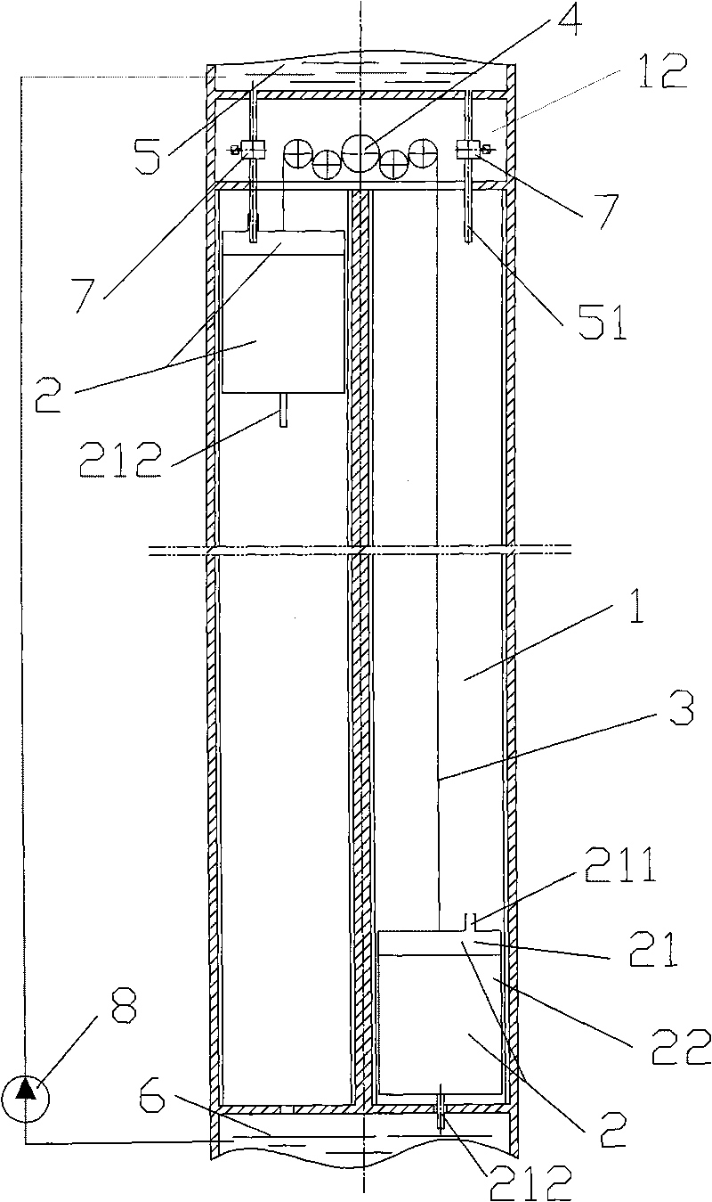
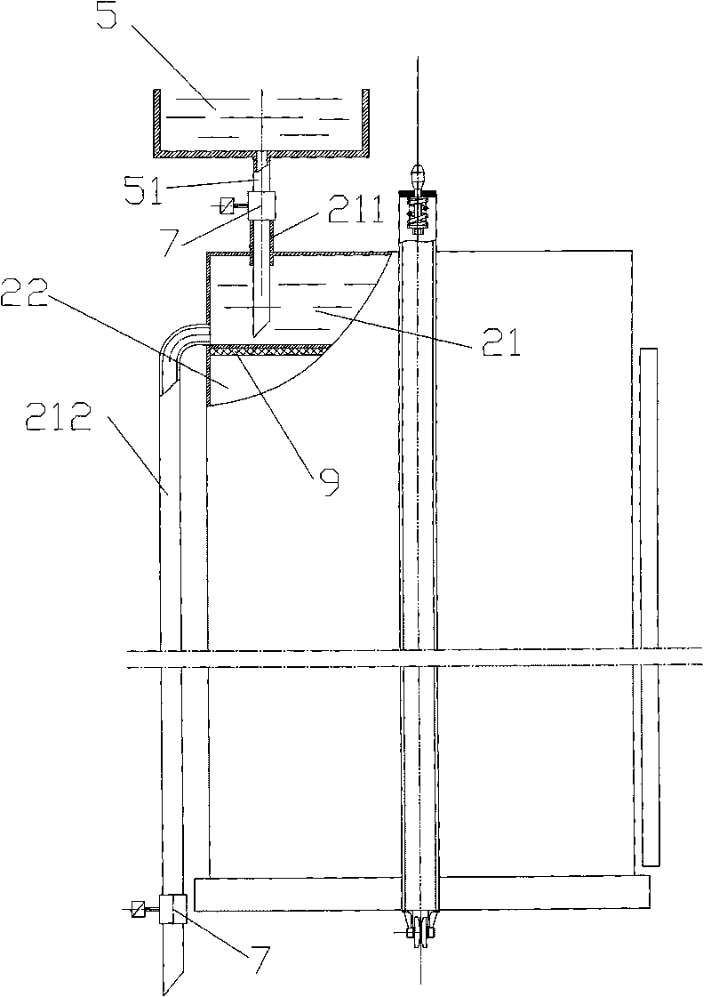
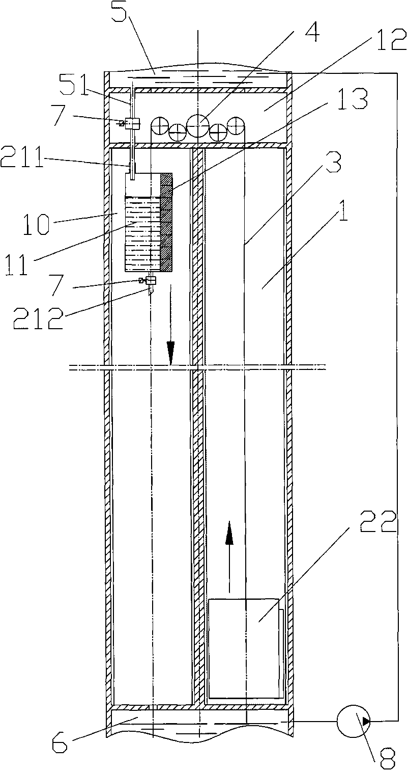
[0026] figure 1 and 2 As shown, the energy storage type vertical elevator for passenger and cargo transport of the present invention comprises a machine shaft 1, two elevator boxes 2 and a machine room 12 on the machine shaft 1, the elevator box 2 is composed of a water tank 21 and a car 22, and the water tank 21 is located on the car 22 , the water tank 21 is provided with a water inlet pipe 211 and a drain pipe 212, and the two elevator boxes 2 are connected by a steel wire rope 3, and the steel wire rope 3 is wound on the hub wheel group 4 in the machine room 12, and a water injection pipe is provided on the top of the machine room 12 The reservoir 5 of 51, the bottom of machine well 1 is provided with drain pool 6, is connected with electromagnetic valve 7 on water injection pipe 51 and drain pipe 212 respectively. A water pump 8 is provided between the water storage tank 5 and the drain tank 6 . Between the car 22 and the water tank 21,...


PUM


Abstract

The invention discloses an energy storage type passenger and freight transportation vertical conveyer, comprising two driven wells and two ladder boxes. Each ladder box comprises a water box and a lift cage, the water box is arranged on the lift cage and is provided with a water intake pipe and a drainage pipe, the two ladder boxes are connected by steel wire ropes, the steel wire ropes are wound on a hub wheel set in a machine room, an impounding reservoir with a water injection pipe is arranged on the top of the machine room, and discharge bays are arranged in the bottoms of the driven wells. The invention also discloses an energy storage type passenger and freight transportation vertical conveyer, comprising a driven well, a balance weight well, a lift cage and a weight balance water box; a lift cage is arranged in the driven well, the balance weight water box is arranged in the balance weight well, wherein the balance weight water box is provided with a water intake pipe and a drainage pipe, the lift cage is connected with the balance weight water box through steel wire ropes, the steel wire ropes are wound on a hub wheel set in a machine room, an impounding reservoir with a water injection pipe is arranged on the top of the machine room, and a discharge bay is arranged at the bottom of the balance weight well. The invention has the advantages of completely avoiding trapping in the conveyer phenomenon caused by power failure, saving energy sources and reducing operating cost by utilizing the transformation of the potential energy of the water in the impounding reservoir into the kinetic energy used for driving the conveyer.

Description

technical field [0001] The invention relates to an elevator, in particular to an energy storage vertical elevator for transporting passengers and goods. Background technique [0002] The elevator relies on the wire rope and the wire rope winch mechanism to drive the ladder box and the counterweight to move up and down between the floors, so as to achieve the purpose of vertically transporting passengers and goods. The biggest disadvantage of the elevator is the wire rope hoisting mechanism. Its load changes greatly during one lifting stroke of the elevator. Ascending, there is no inertial force, followed by torque; the car decelerates upwards, the inertial force and gravity are reversed, and the torque is the second; when descending, the weight of the car and its passengers and cargo becomes the power of the wire rope hoisting mechanism, and sometimes even makes the wire rope hoisting mechanism The torque becomes a negative value and needs to be processed. Due to the serio...

Claims


Application Information

Patent Timeline
Patent Type & Authority Applications(China)
IPC IPC(8): B66B9/00B66B11/08
CPCY02B50/148Y02B50/146Y02B50/00
Inventor 舒先达
Owner 舒先达
Why Eureka
Try Eureka