
Combined semi-directly driven wind-powered speed increasing box

A combined, semi-direct drive technology, applied in wind power generation, transmission boxes, wind turbines, etc., can solve the problem of maintenance. The entire wind power speed-up box must be disassembled from the top of the tower before repairing and increasing the speed-up box. The burden of the manufacturer, the difficulty of equipment transportation and installation, etc., to achieve the effect of shortening the mechanical transmission chain, improving the overall performance, and increasing the service life

Inactive Publication Date: 2011-04-13
汇洲智能技术集团股份有限公司
View PDF9 Cites 0 Cited by
  • Summary
  • Abstract
  • Description
  • Claims
  • Application Information

AI Technical Summary

Problems solved by technology

[0005] 1. Since wind turbines must be installed in areas with rich wind resources such as mountains, wilderness, beaches, islands, etc., the natural environment of wind turbines is poor and the transportation is inconvenient, which brings great difficulties to the transportation and installation of equipment. Difficulties
In the existing wind turbines, this type of integral wind power gearbox is installed in the narrow space of the tower top cabin. Once the wind power gearbox fails, it cannot be directly repaired in the tower top cabin, and the entire wind power gearbox must be replaced. Repair after removal from the tower top
Due to the large volume and weight of this type of wind power speed-up box, only a special giant crane can be used to hoist the wind power speed-up box on the top of the tower to the ground, and then repair the wind power speed-up box. The cost is as high as hundreds of thousands of yuan, and it will consume more human and material resources, thereby increasing the production cost and increasing the burden on the manufacturer of the gearbox
[0006] 2. In the traditional one-stage planetary and two-stage parallel shaft cylindrical gear transmission gearbox, due to the structural characteristics of the helical inner ring gear, planetary gear, and sun gear meshing in sequence, the cylindrical roller bearing supporting the planetary gear is determined to be In addition to bearing the normal radial load, it also always bears the effect of torsional moment, which causes the cylindrical roller bearing to be unbalanced, aggravates the wear of the bearing, and easily causes damage to the planetary gear. This part becomes the link with the highest failure rate in the gearbox
For example, the date of application is August 30, 2006, and the announcement number is CN200943679. In the Chinese patent, a disclosed wind power speed-up box is exactly this type of wind power speed-up box. The planetary wheels and bearings in the speed-up box are very easy to Damaged, requiring frequent repairs, making the overall performance of the equipment poor
[0007] Although the gearbox manufacturers continue to adopt new technologies and new processes to improve the product quality of the gearbox, since the gearbox is the main carrier of power transmission for wind turbines, under harsh working conditions such as strong impact loads, the gearbox It is still the component with the highest failure rate in wind turbines. Manufacturers of gearboxes pay a large amount of compensation every year for the losses caused by the downtime of gearbox failures, making it difficult for some manufacturers to maintain production
[0008] At present, there are also some wind power gearboxes that use two-stage parallel shaft cylindrical gear pairs. The structure of this type of wind power gearbox is extremely complicated, often using a large number of wearing parts such as bearings and gears, and using a heavy main shaft structure instead of Connecting with the external wind wheel hub not only enlarges the size and weight of the wind power gearbox, but also consumes more raw materials in the equipment manufacturing process, which increases the production cost of the equipment

Method used


Image

  • Combined semi-directly driven wind-powered speed increasing box
  • Combined semi-directly driven wind-powered speed increasing box
  • Combined semi-directly driven wind-powered speed increasing box

Examples


Embodiment

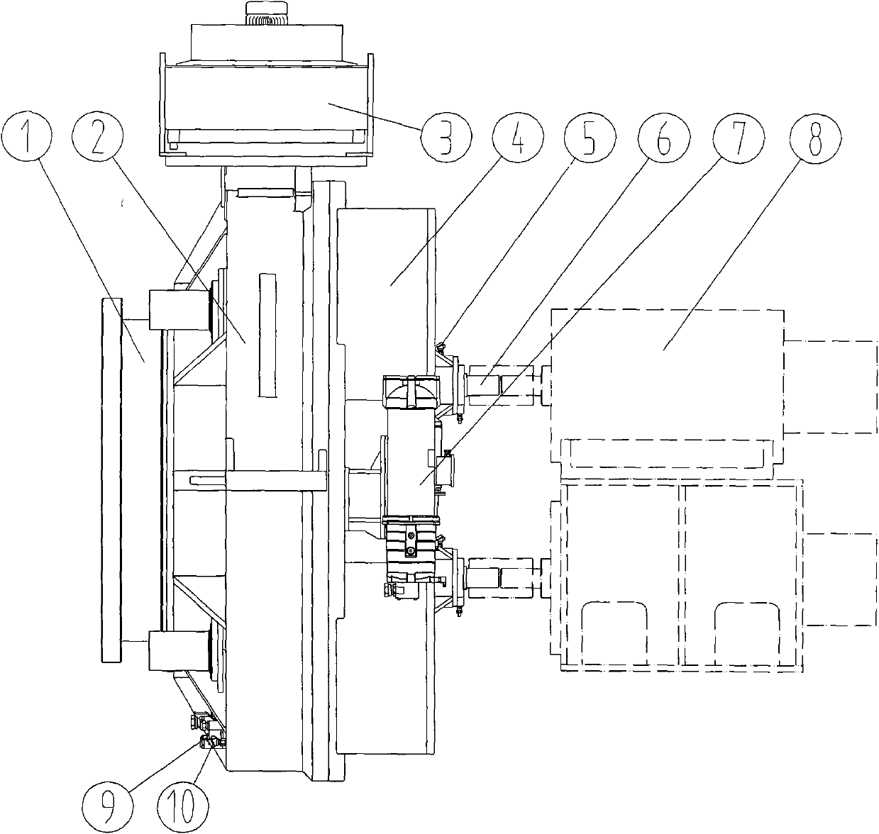
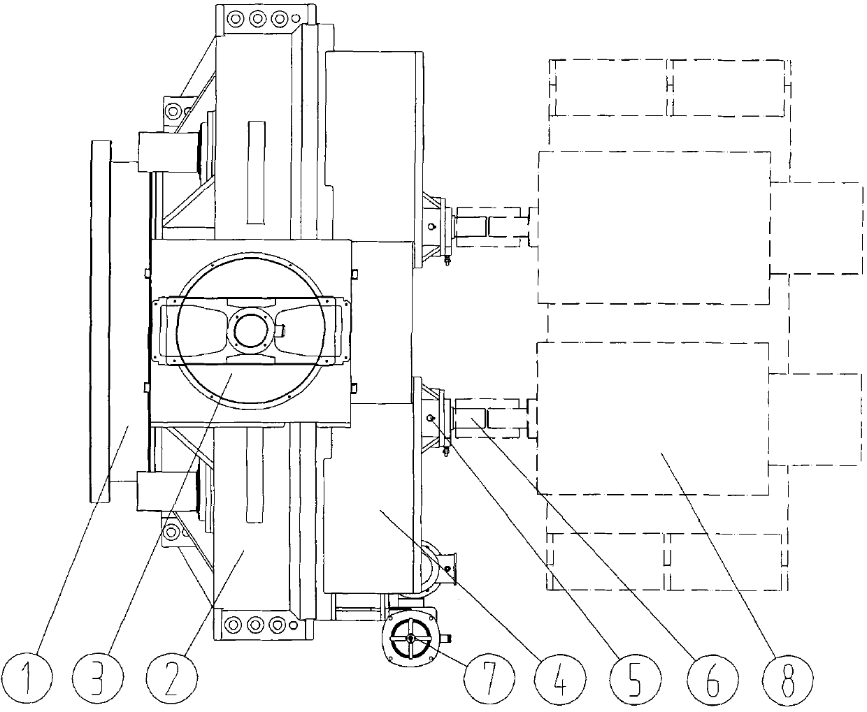
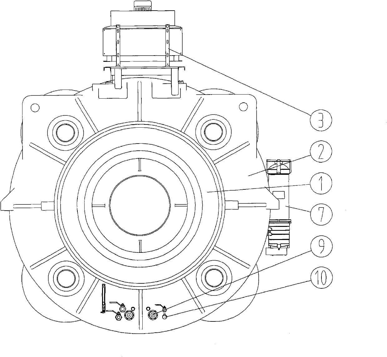
[0037] see Figure 1 to Figure 5 , the combined semi-direct drive wind power gearbox in this embodiment is composed of an air cooling device 3, an oil supply filter device 7, a temperature control device, a primary speed-up body and a secondary speed-up body, wherein the temperature control device includes a bearing Temperature sensor 5, electric heater 9 and oil temperature sensor 10.

[0038] The first-stage speed-increasing body in this embodiment includes a coupling body 1, a primary box body 2, a combined tapered roller bearing 11, a large ring gear 13 and four gear shafts 14 with brake discs 12, wherein the coupling body 1 It is a hollow barrel structure, which greatly reduces the overall weight of the primary speed-increasing body. The combined tapered roller bearing 11 in this embodiment is installed in the primary box 2, the inner ring of the combined tapered roller bearing 11 can rotate, the large ring gear 13 is located in the primary box 2, and the connecting body...


PUM


Abstract

The invention relates to a combined semi-directly driven wind-powered speed increasing box, which belongs to a component in a wind generating set. At present, no wind-powered speed increasing box with a simple structure and long service life exists. The combined semi-directly driven wind-powered speed increasing box comprises an air cooling device, an oil supply filtering device and a temperaturecontrol device, wherein the combined semi-directly driven wind-powered speed increasing box further comprises a first-stage speed increasing body and a second-stage speed increasing body; and the first-stage speed increasing body comprises a first-stage box body, a combined conical roller bearing, a big gear ring, a connecting body and a gear shaft, wherein the combined conical roller bearing is fixed in the first-stage box body; the big gear ring is positioned in the first-stage box body and is fixed with the connecting body; the gear shaft is installed in the first-stage box body; the second-stage speed increasing body comprises a second-stage box body and a second-stage transmission device; the second-stage transmission device consists of a second-stage gear and an output gear; and thefirst-stage box body is fixed with the second-stage box body. The combined semi-directly driven wind-powered speed increasing box has reasonable and simple design, high reliability, easy assembly anddisassembly and easy maintenance.

Description

technical field [0001] The invention relates to a wind power speed-up box, in particular to a combined semi-direct drive wind power speed-up box, which belongs to a component of a wind power generating set, and is a combined type with compact structure, high reliability, and easy disassembly and maintenance. The semi-direct drive wind power gearbox is used in the field of wind power generation technology, and is especially suitable for high-power semi-direct drive permanent magnet wind turbines above 1.5MW. Background technique [0002] The wind power gearbox is an important mechanical part of the wind power generating set. Its main function is to transmit the power generated by the wind rotor blades under the action of the wind to the generator, and make the generator obtain a corresponding speed, so as to realize the power generation function of the generator. . Usually, the speed of the wind rotor is very low, which is far below the speed required by the generator for po...

Claims


Application Information

Patent Timeline
Patent Type & Authority Patents(China)
IPC IPC(8): F16H57/04F03D11/00F16H57/02F03D15/00F16H57/023
CPCY02E10/72Y02E10/722
Inventor 马兴法时大方俞文海
Owner 汇洲智能技术集团股份有限公司
Learn More