Feeding conveyer for machining of large workpiece

A technology for large workpieces and conveyors, applied in the direction of conveyors, mechanical conveyors, transportation and packaging, etc., it can solve the problem that it is difficult to meet the requirements of straightness and stability, metal workpieces are not allowed to be finished, and the speed of workpieces and power rollers Poor problems, to achieve the effect of simple structure, low manufacturing cost, and good straightness of motion

Inactive Publication Date: 2011-05-25
CHONGQING UNIV
View PDF5 Cites 9 Cited by
  • Summary
  • Abstract
  • Description
  • Claims
  • Application Information

AI Technical Summary

Problems solved by technology

However, there are many hinge points in the chain conveyor, and it is easy to form a large cumulative error. Therefore, the machining accuracy of the chain link components must be improved, which will increase the manufacturing cost. At the same time, the hinge joints are easy to wear, which affects the reliability of use. Many small roller bearings make maintenance difficult
[0004] The problem with the power roller conveyor as a feeding and conveying device for mechanical processing is that the workpiece and the roller table are rolling relative to each other. Due to the small rolling friction force, the workpiece is equivalent to floating on the roller, but in the feeding and conveying flow water of large workpieces , it is often necessary to use two rows of rollers, the linear speed of the two rows of rollers may not be consistent due to the error of processing and installation, so it is difficult to meet the requirements of straightness and stability
In addition, because the power roller table itself is driven by several motors independently or in groups, the linear speed at which the power roller table touches the workpiece surface cannot be completely consistent, that is to say, each power roller table cannot be completely consistent with the running speed of the workpiece. There is a speed difference between the workpiece and the power roller table, which will inevitably lead to wear on the surface of the workpiece. This has no effect in the metal rough machining stage, but for workpieces with high surface quality requirements, the power roller table will inevitably damage the surface of the workpiece as a feeding device. This is not allowed for post-finishing of metal workpieces

Method used


Image

  • Feeding conveyer for machining of large workpiece
  • Feeding conveyer for machining of large workpiece
  • Feeding conveyer for machining of large workpiece

Examples


Embodiment Construction

[0022] In order to facilitate the understanding of the intention of the present invention, the intention of the invention will be further described below through the examples, but the intention of the invention is not limited by the examples.

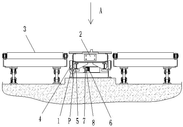
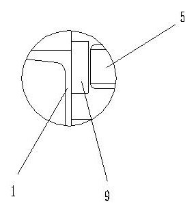
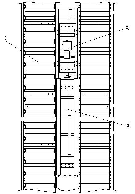
[0023] figure 1 It is a schematic diagram of the overall structure of the large-scale workpiece processing feed conveyor of the present invention; figure 2 for figure 1 Middle P enlarged view; image 3 for figure 1 The A-direction view, the direction indicated by the arrow in the figure is the forward direction of the conveyor; Figure 4 Front view of the driving car.

[0024] As shown in the figure, the feeding conveyor for processing large workpieces of the present invention includes a track 1 and a driving car 2 for carrying and driving the workpiece to move along the track. The driving car 2 is arranged on the track in a manner that can reciprocate along the track 1 superior. The workpiece is conveyed by the driving car movin...


PUM


Abstract

The invention discloses a feeding conveyer for the machining of a large workpiece, which comprises a track and a driving vehicle, wherein the driving vehicle is used for bearing and driving the workpiece to move along the track and is arranged on the track by moving to and fro along the track. The feeding conveyer for the machining of the large workpiece has no relative sliding between the workpiece and the driving vehicle and can not cause damage to the surface of the workpiece by conveying the workpiece through the driving vehicle moving along the track, and also has a high feeding precision and a simple structure, has no complex transmission mechanism, has a few vulnerable components, a low failure rate during running and a low manufacturing cost and is convenient to maintain; non-powered roll tables on two sides of the driving vehicle make the workpiece be more stable in the running process and overcome the defect of inconsistent linear speed of live rollers on a powered roll table; the non-powered roll tables and the workpiece have no relative sliding therebetween, so no damage on the workpiece can be caused; the positive pressure between the workpiece and the driving vehicle, and between the workpiece and the roll tables can be regulated by regulating the height of the non-powered roll tables, so that the driving vehicle can work under the optimal working condition, the sliding of the workpiece is avoided and the stable feeding is ensured.

Description

technical field [0001] The invention relates to a conveying device, in particular to a feeding and conveying device for a large workpiece during processing. Background technique [0002] In the process of modern industrial processing and manufacturing, especially the dynamic assembly process of large-scale mechanical products, it is often necessary to use the movement of the conveyor to transport large workpieces as a feed movement. In this case, the conveyor becomes an important part of the machine tool , which becomes the feed mechanism of the machine tool. To achieve the processing quality required by the product, the running straightness and stability of the conveyor should meet the needs of mechanical processing, otherwise, the processed product will not meet the quality requirements, and it should also have reliable operation, low failure rate, Small manufacturing cost and other characteristics to enhance its market competitive advantage. [0003] There are two types...

Claims


Application Information

Patent Timeline
Patent Type & Authority Applications(China)
IPC IPC(8): B65G35/00
Inventor 朱才朝冉险生杜雪松张斌吴世春
Owner CHONGQING UNIV
Why Eureka
Try Eureka