Novel overspeed petective slide valve

An overspeed protection, slide valve technology, applied in the direction of fluid pressure actuation device, fluid pressure actuation system safety, mechanical equipment, etc. The effect of low cost, short response time and convenient setting

Active Publication Date: 2006-03-22
HANGZHOU HOLLYSYS AUTOMATION
View PDF0 Cites 9 Cited by
  • Summary
  • Abstract
  • Description
  • Claims
  • Application Information

AI Technical Summary

Problems solved by technology

[0003] For the overspeed protection device with mechanical structure, its structure is relatively complicated, and it needs to be pre-adjusted when it is static, and calibrated when the equipment is running, which needs to be completed after 2-3 startups and adjustments
If overspeed does not occur for a long time, the parts are easy to rust and get stuck; and the overspeed protection device with electrical structure, although its structure is relatively simple, is easily affected by external interference and affects reliability, and due to the existence of sampling time, the dynamic response slower

Method used


Image

  • Novel overspeed petective slide valve
  • Novel overspeed petective slide valve

Examples


Embodiment 1

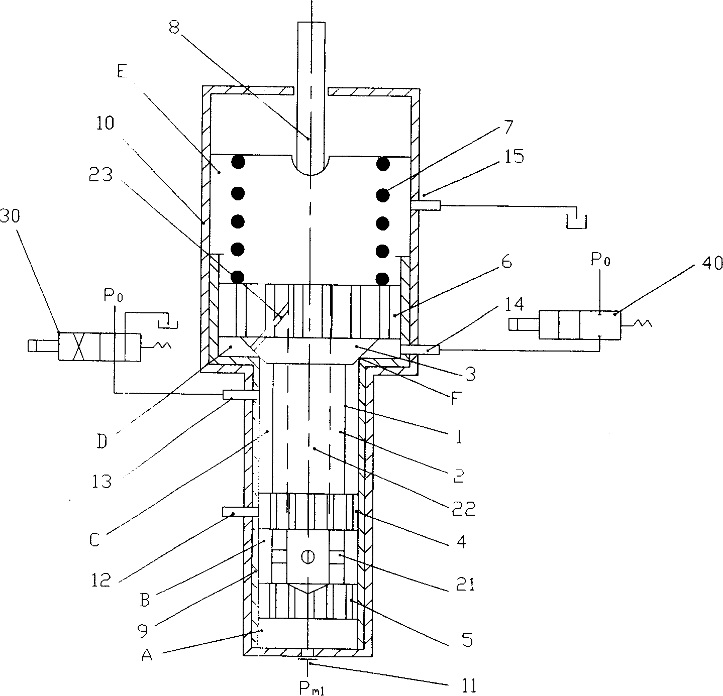
[0021] figure 1 It is a schematic diagram of the structure of the overspeed protection slide valve when the rotary damper is used as the speed sensitive element of the turbine shaft. The rotary damper converts the speed signal of the rotating shaft into a pulsating oil pressure signal, and its output pressure P m1 It acts on the lower end face of the spool 1 of the overspeed protection spool. P 0 Oil pressure is the external pressure oil source. The overspeed protection spool valve includes a valve core 1 , a spring 7 , a setting screw 8 , a valve sleeve 9 and a housing 10 . The valve sleeve 9 is fitted tightly with the lower inner surface of the housing 10 . The spool 1 is a multi-shoulder stepped structure, located in the inner cavity of the valve sleeve 9; the spool 1 has a shaft core 2 and an upper shoulder 6, a tapered surface 3, a middle Shoulder 4 and lower shoulder 5 . The diameters of the middle shoulder 4 and the lower shoulder 5 are equal, and the diameter of ...

Embodiment 2

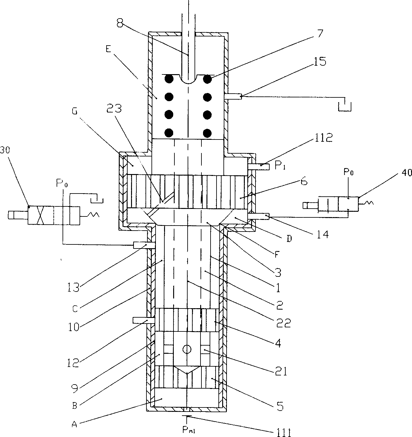
[0028] refer to figure 2 , is the structural diagram of the overspeed protection slide valve when the speed regulating pump is used as the speed sensitive element of the rotating shaft. The speed regulating pump is a radial drilling pump, which converts the speed signal of the rotating shaft into a pulsating oil signal. The difference from Embodiment 1 is that the rotational speed signal of the radial drilling pump is the outlet oil pressure and the inlet oil pressure of the pump. The signal received by the spool 1 of the overspeed protection spool is the difference between the outlet and inlet oil pressure of the pump. In this figure, P 0 is the oil pressure of the external pressure oil source, P m1 is the outlet oil pressure of radial drilling pump, P 1 is the inlet oil pressure of the radial drilling pump, that is, the pressure return oil.

[0029] The sliding core 1 of the spool valve in this embodiment also extends for a section above the upper shoulder 6, and another...


PUM


Abstract

The novel overspeed protection slide valve includes casing, valve lining, valve core, spring and its setting mechanism. The valve core in stepped structure may be move in two, including one upper and one lower, positions inside the valve lining cavity. When it is in the lower position, the valve core, the inner valve lining wall and the casing form separate primary pulsed oil cavity chamber, oil exhaust chamber, repositioning oil chamber, inverse and forward oil feeding chamber and spring chamber communicated to the oil exhaust chamber via the valve core hole. When the valve core moves to the upper position, the repositioning oil chamber is communicated to the inverse and forward oil feeding chamber. The valve lining and the casing are provided with primary pulsed oil inlet, safety oil port, repositioning oil port, test oil port and no-pressure oil back port, and the safety oil port is closed while the valve core is in the lower position and is communicated to oil exhaust chamber while in the upper position.

Description

technical field [0001] The invention relates to a novel overspeed protection slide valve, which belongs to the field of hydraulic control systems. Background technique [0002] For high-speed rotating machines such as steam turbines, the inertia moment of the rotor is generally small relative to the driving torque. Once the unit is in operation and suddenly disconnects from the power grid to remove all electrical loads, the huge driving torque of the steam turbine acts on the rotor, causing the speed to rise rapidly. If the judgment and treatment are not made in a timely, fast and reliable manner, the speed will exceed the limit speed allowed by safety, resulting in a vicious accident of destroying the machine. Therefore, to ensure high-speed rotating machinery, an overspeed protection device is often provided. Currently commonly used for the mechanical structure and electrical structure. [0003] For the overspeed protection device with mechanical structure, its structure...

Claims


Application Information

Patent Timeline
Patent Type & Authority Applications(China)
IPC IPC(8): F15B20/00
Inventor 罗作桢
Owner HANGZHOU HOLLYSYS AUTOMATION
Why Eureka
Try Eureka