Integrated control mechanism for automatic walking device clutch and continuously variable transmission of lawn mower

A technology of continuously variable transmission and control mechanism, which is applied to harvesters, agricultural machinery and implements, and the chassis of agricultural implements, etc., to achieve the effect of simple structure and ingenious conception

Inactive Publication Date: 2010-04-28
NINGBO DELIN MACHINERY
View PDF1 Cites 14 Cited by
  • Summary
  • Abstract
  • Description
  • Claims
  • Application Information

AI Technical Summary

Problems solved by technology

[0002] The self-propelled lawnmowers of the prior art either have a clutch mechanism or a continuously variable transmission mechanism, which are respectively controlled by drag cables. This is a technical solution familiar to the public. machine, such as the small self-propelled walking mower of 200710007178.9 disclosed in the Chinese patent literature announcement, which discloses the structure of the mower, and the working state of the mower is controlled by the hand-held operating mechanism and the clutch handle. The handle is only used to change gears

Method used


Image

  • Integrated control mechanism for automatic walking device clutch and continuously variable transmission of lawn mower
  • Integrated control mechanism for automatic walking device clutch and continuously variable transmission of lawn mower
  • Integrated control mechanism for automatic walking device clutch and continuously variable transmission of lawn mower

Examples


Embodiment Construction

[0022] The embodiments of the present invention will be described in detail below in conjunction with the accompanying drawings.

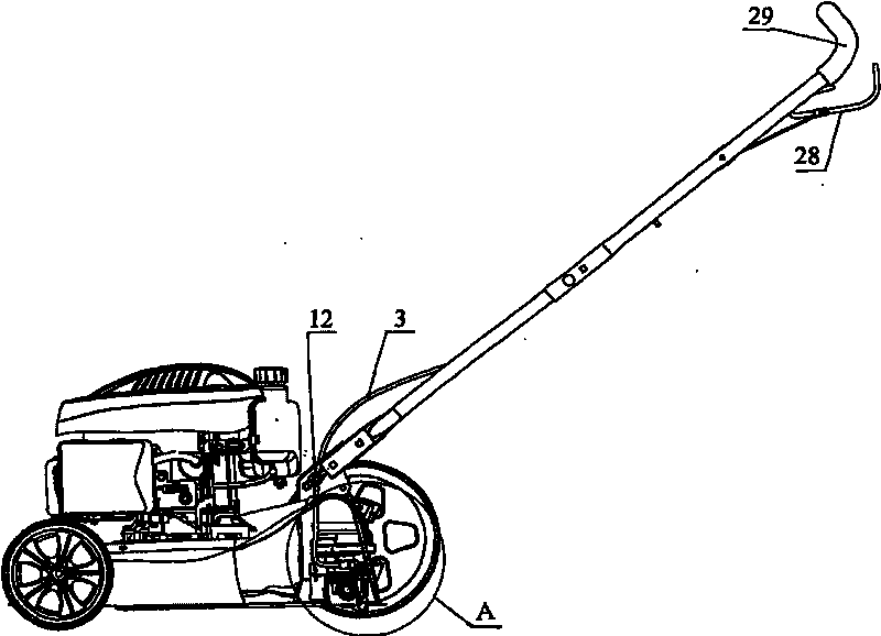
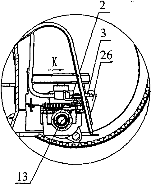
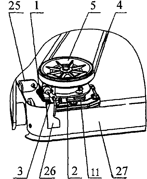
[0023] Such as Figure 1-7 As shown in the figure, 1. return tension spring, 2. stroke plate, 3. cable, 4. belt, 5. pulley, 6. small bevel tooth, 7. oil seal I, 8. box cover, 9. double row angle Contact bearing, 10. Hole retaining ring, 11. Reset torsion spring, 12. Cable hole, 13. Drive shaft, 14. Oil seal II, 15. Thrust bearing, 16. Compression spring, 17. Shaft retaining ring, 18. Large Gasket, 19. Shift fork, 20. Elastic cylindrical pin, 21. Clutch, 22. Large bevel tooth, 23. Box body, 24. Fixed guide sleeve, 25. Fixed plate, 26. Cable fixed plate, 27. Chassis , 28. CVT pull rod, 29. Handrail, 30. Guide key, 31. Key, 32. Groove.

[0024] The integrated control mechanism of the self-propelled clutch of the lawn mower and the continuously variable transmission, the control mechanism is provided with a continuously variable transmission pull rod...


PUM


Abstract

The invention relates to an integrated control mechanism for an automatic walking device clutch and a continuously variable transmission of a lawn mower, which comprises a variable speed pulling rod, a pulling cable, a pulling cable fixing plate, a stroke plate, a belt pulley, a belt, and a small bevel gear, a large bevel gear, a return torsional spring, a return tension spring, a shifting fork, a clutch, a driving shaft, a compression spring and the like which are arranged in a chamber consisting of a box body and a box cover. When the integrated control mechanism is controlled, the variable speed pulling cable drives the stroke plate to drive the shifting fork so as to push the clutch to axially move through counter pull of the pulling cable fixing plate; and the clutch is meshed with the large bevel gear by combining elastic force of the compression spring on the driving shaft so as to drive the driving shaft to rotate. When the pulling cable is loosened, the shifting fork drives the clutch to separate from the large bevel gear in a reverse direction. Meanwhile, the integrated control mechanism achieves variable speed through clenching degree of the belt pulley and the belt, achieves integrated control of one pulling cable and has the advantages of ingenious design and simple structure.

Description

technical field [0001] The invention relates to a clutch mechanism of a self-propelled mower or a control mechanism of a continuously variable transmission, in particular to an integrated control mechanism of a clutch of a self-propelled lawn mower and a continuously variable transmission. Background technique [0002] The self-propelled lawn mowers of the prior art either have a clutch mechanism or a continuously variable transmission mechanism, which are respectively controlled by drag cables. This is a technical solution familiar to the public. machine, such as the small self-propelled walking mower of 200710007178.9 disclosed in Chinese patent literature, which discloses the structure of the mower, and the working state of the mower is controlled by the hand-held operating mechanism and the clutch handle. The handle is for changing gears only. How to simultaneously control the lawn mower self-propelled clutch and continuously variable transmission through a cable to for...

Claims


Application Information

Patent Timeline
Patent Type & Authority Applications(China)
IPC IPC(8): A01D67/00A01D69/06
Inventor 陆立孟
Owner NINGBO DELIN MACHINERY
Why Eureka
Try Eureka