

Mold heating and cooling rod and mold capable of realizing rapid cooling and rapid heating
A mold heating and cooling rod technology, which is applied in the field of mold heating and cooling rods and molds that can realize rapid cooling and rapid heating, can solve the problems of flow marks, shrinkage, surface foaming, etc., and achieve improved fluidity, reduced pressure, Good heat insulation effect
- Summary
- Abstract
- Description
- Claims
- Application Information
AI Technical Summary
Problems solved by technology
Method used
Image

Examples
Embodiment 1
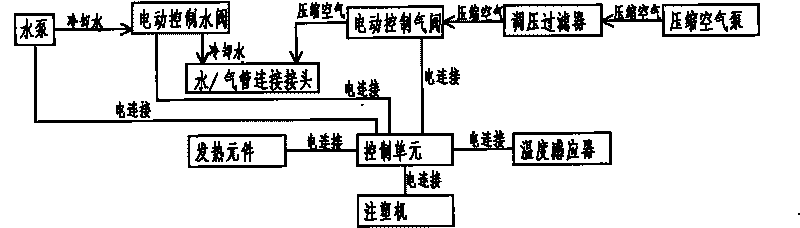
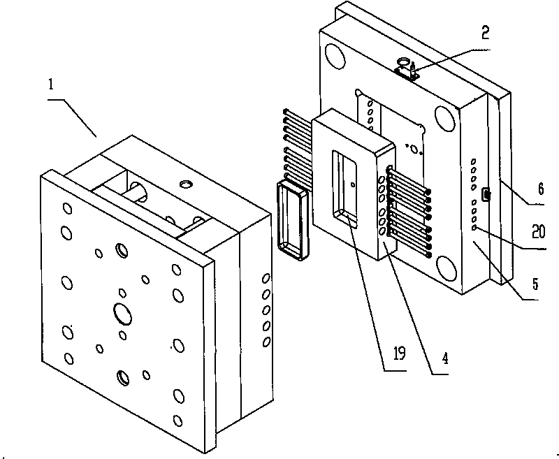
[0060] Such as figure 1 As shown, a mold that can realize rapid cooling and rapid heating includes a control unit electrically connected to the injection molding machine, a water pump electrically connected to the control unit, a heating element, a temperature sensor, an electric control water valve, an electric control air valve, and an electric control unit. The control air valve is connected to the pressure regulating filter and the water / air pipe connection joint through the air pipe, and the electric control water valve is connected to the water pump and the water / air pipe connection joint through the water pipe. The water / air pipe connection joint is installed in the cooling heat insulation hole and the heat insulation cooling hole and communicate with the cooling heat insulation hole and the heat insulation cooling hole; the pressure regulating filter is connected with the compressed air pump through the air pipe. The mold temperature when heating the cooling rod and t...
Embodiment 2
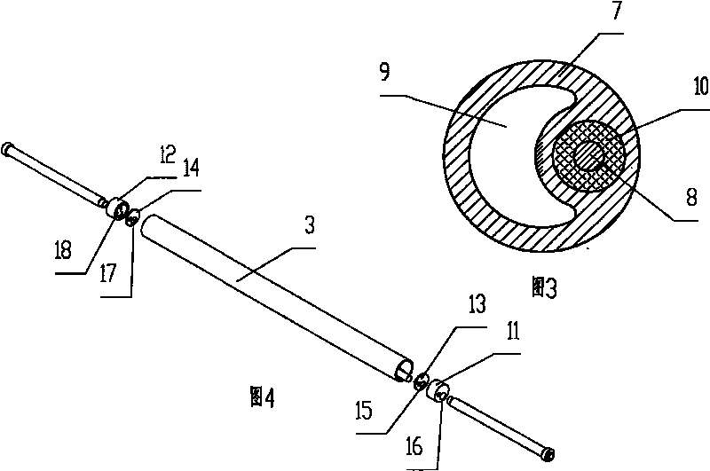
[0067] Such as Figure 5 As shown, different from Embodiment 1, the heating and cooling rod body 31 is cylindrical, the section of the heating element accommodation hole 32 is a sector with a central angle less than 180°, and the section of the cooling and heat insulation hole 33 is a sector with a central angle greater than 180° , the cooling and heat insulation hole 33 surrounds the heating element accommodating hole 32 from three directions. The temperature sensor 34 is arranged at one end of the heating and cooling rod body 31 and extends into the heating and cooling rod body 31 .
Embodiment 3
[0069] Such as Figure 6 As shown, the difference from Embodiment 1 is that the heating and cooling rod body 41 is cylindrical, the section of the heating element accommodation hole 42 is similar to a semicircle, the section of the cooling and heat insulation hole 43 is similar to a semicircle, and the cross section of the cooling and heat insulation hole greater than the cross-section of the heating element.
PUM
 Abstract
Description
Claims
Application Information