Rigid integral dropper of overhead contact line equipment of electrified railway

An electrified railway and catenary technology, applied in the direction of overhead lines, etc., can solve the problems of hanging string ablation, poor current-carrying state, burning loss, etc., to prevent electrical corrosion, overcome the contact line dancing with the wind, and eliminate potential poor effect

Inactive Publication Date: 2010-04-28
汉和飞轮(北京)电气化器材有限公司
View PDF0 Cites 6 Cited by
  • Summary
  • Abstract
  • Description
  • Claims
  • Application Information

AI Technical Summary

Problems solved by technology

[0003] The purpose of the present invention is to provide a rigid integral hanging string of the electrified railway catenary, which solves the problem that the current-carrying coordination state of the existing integral hanging string is not smooth, which leads to the ablation and burning of the hanging string, and ensures the power components of the catenary security

Method used


Image

  • Rigid integral dropper of overhead contact line equipment of electrified railway
  • Rigid integral dropper of overhead contact line equipment of electrified railway
  • Rigid integral dropper of overhead contact line equipment of electrified railway

Examples


Embodiment Construction

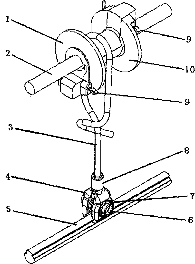
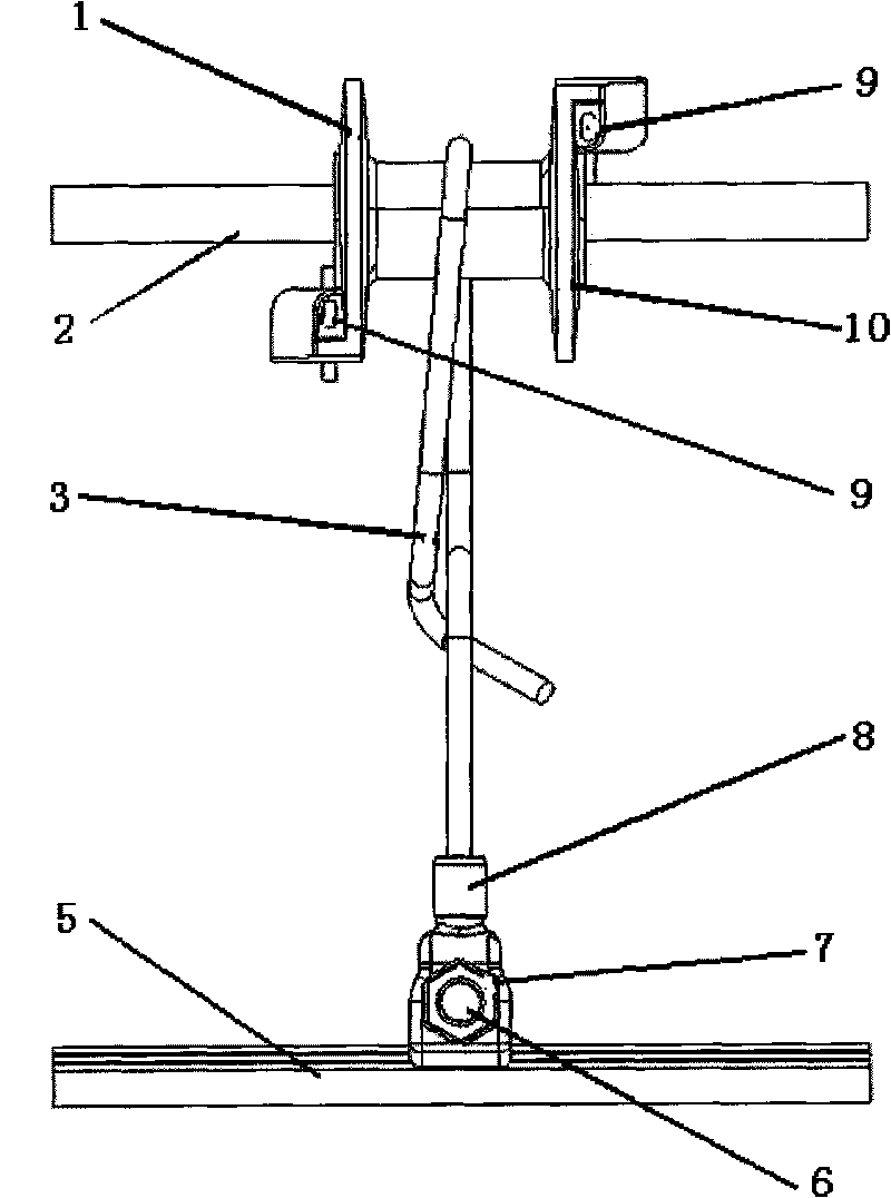
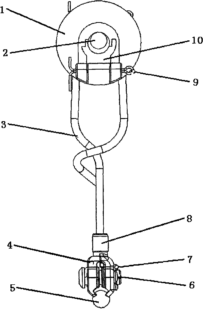
[0017] The present invention will be described in detail below in conjunction with the accompanying drawings and specific embodiments.

[0018] The structure of the rigid integral hanging string of the present invention, such as figure 1 , figure 2 and image 3 shown. It includes an "I"-shaped sleeve assembled from the sleeve A piece 1 and the sleeve B piece 10. Sleeve A piece 1 and sleeve B piece 10 are saddle-shaped structures, with semicircular grooves along the axial direction, discs are respectively arranged at one end, and a groove is respectively opened on the discs along the radial direction. They respectively communicate with the semicircular grooves in the axial direction of sleeve A piece 1 and sleeve B piece 10. Two protrusions are respectively arranged on the outer surfaces of the discs on both sides of the groove, and there are holes on the protrusions. Two circular through holes, the two circular through holes are located on the same axis, forming a one-to-...


PUM


Abstract

The invention discloses a rigid integral dropper of overhead contact line equipment of a high-speed electrified railway, which comprises an I-shaped sleeve made of an insulating material, wherein the sleeve is provided with a through hole along the axial direction; disks at two ends of the sleeve are provided with grooves communicated with the through hole of the sleeve along the radius direction respectively, and the two grooves are positioned in a 180-degree direction; inserted blocks made of the insulating material are arranged in the two grooves respectively; a dropper line is hung on a middle section of the sleeve and is n-shaped; one end of the dropper line is fixedly connected with a clamping piece A of the dropper line; and the clamping piece A of the dropper line is fixedly connected with a clamping piece B of the dropper line. The rigid integral dropper can ensure the reserved looseness of a contact wire so that when a pantograph of a locomotive obtains current, offline phenomena cannot be generated due to an unsmooth contact wire, and simultaneously double insulation is formed between a catenary wire and the contact wire to effectively eliminate the potential difference between the catenary wire and the contact wire and prevent the electric corrosion of dropper line.

Description

technical field [0001] The invention belongs to the technical field of an electrified railway catenary system, and relates to a rigid integral hanging string of an electrified railway catenary. Background technique [0002] The catenary wire of the electrified railway catenary system sags due to its own weight, which seriously affects the safe operation of the electric locomotive. Therefore, a load-bearing hanging string is installed between the catenary wire and the catenary cable to keep the catenary line in a horizontal state. The load-bearing suspension string of electrified railway catenary is a very important part in the catenary. Its local failure will increase the load of the adjacent suspension string, thus forming a vicious circle and causing serious accidents. Link hanging strings have low mechanical strength and short service life, often have virtual contact when connected to catenary, and are prone to electrical loss, which has been gradually replaced by integra...

Claims


Application Information

Patent Timeline
Patent Type & Authority Applications(China)
IPC IPC(8): B60M1/23
Inventor 李霁开
Owner 汉和飞轮(北京)电气化器材有限公司
Why Eureka
Try Eureka