Distribution system of magnetic supports in vacuum glass

A vacuum glass and support technology, applied in glass forming, glass remolding, glass manufacturing equipment and other directions, can solve the problems of high error rate and low efficiency, achieve high deployment efficiency, reduce manufacturing costs, and deploy The effect of low error rate

Inactive Publication Date: 2010-04-28
黑龙江省农业科学院农村能源研究所
View PDF0 Cites 13 Cited by
  • Summary
  • Abstract
  • Description
  • Claims
  • Application Information

AI Technical Summary

Problems solved by technology

[0004] The purpose of the present invention is to solve the problems of low efficiency and high error rate existing in the placement technology of supports in vacuum glass, and to provide a system for placing magnetic supports in vacuum glass

Method used


Image

  • Distribution system of magnetic supports in vacuum glass
  • Distribution system of magnetic supports in vacuum glass
  • Distribution system of magnetic supports in vacuum glass

Examples


specific Embodiment approach 1

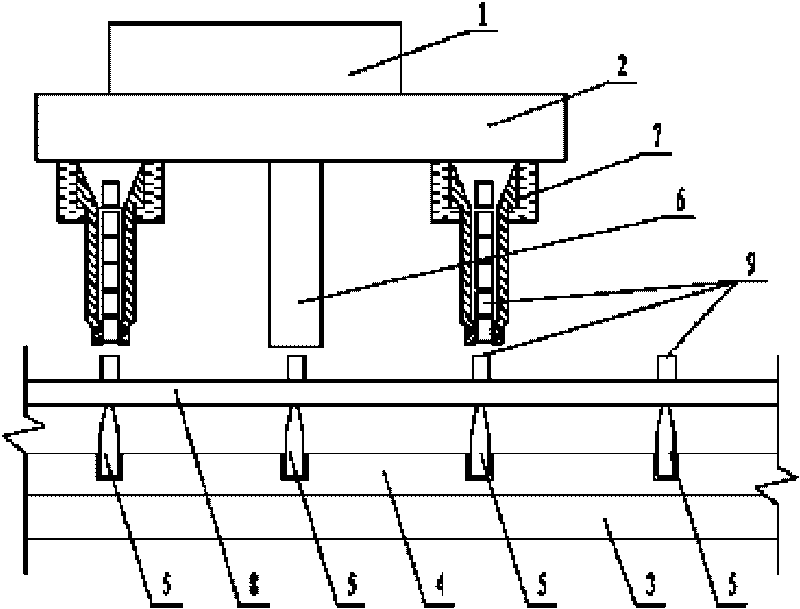
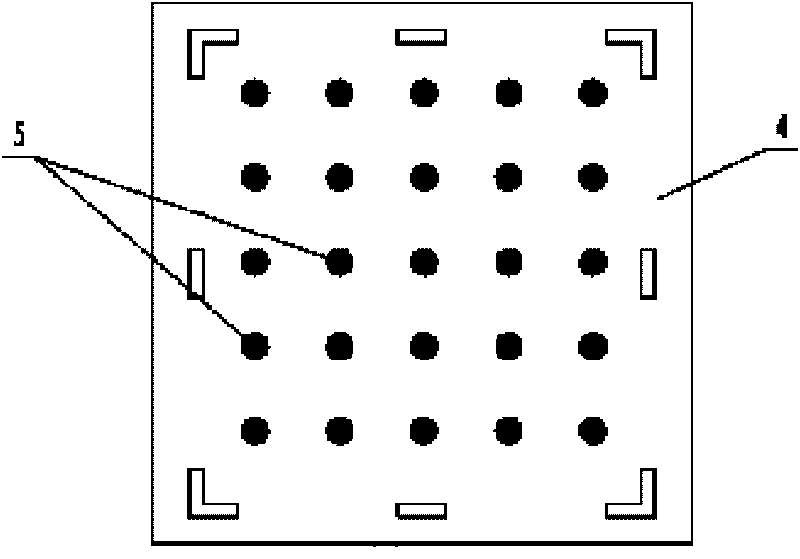
[0008] Specific implementation mode one: combine Figure 1 ~ Figure 2 Describe this embodiment, the system for laying magnetic supports in vacuum glass in this embodiment is composed of a stepping drive motor 1, a movable base 2, a cloth inspection assembly, a placement table 3, an electromagnetic generator 4 and a plurality of magnets 5 Composition, the cloth inspection component package is composed of a photoelectric detection head 6 and two deployment pens 7, an electromagnetic generator 4 is installed on the upper end surface of the deployment platform 3, and the plurality of magnets 5 are evenly arranged on the electromagnetic On the generator 4, the cloth inspection assembly is placed above a plurality of magnets 5, the photoelectric detection head 6 and two deployment pens 7 are installed on the movable base 2, and the photoelectric detection head 6 is located on two Between the placement pens 7, the distance between the photoelectric detection head 6 and each placement...

specific Embodiment approach 2

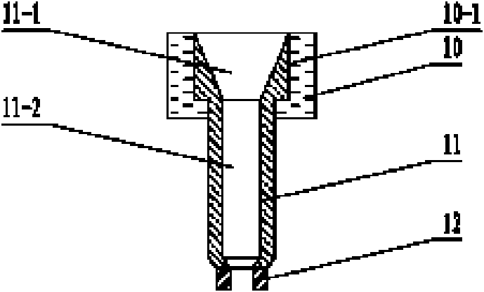
[0010] Specific implementation mode two: combination image 3 and Figure 4 Describe this embodiment, the deployment pen 7 of this embodiment is composed of a base body 10, a housing 11 and two magnetic clamping plates 12, the upper end surface of the base body 10 is provided with a shoulder hole 10-1, and the The upper end of the housing 11 is installed in the shoulder hole 10-1, the upper part of the inner cavity of the housing 11 is a tapered hole 11-1, and the lower part of the inner cavity of the housing 11 is an elongated hole 11-2, so The tapered hole 11-1 is the preparation space for the magnetic support, and the elongated hole 11-2 is the falling space for the magnetic support. The two magnetic clamps 12 are correspondingly arranged on the lower end surface of the housing 11. The distance between the clamping plates 12 is equal to the diameter of the magnetic support 9, and the space between the two magnetic clamping plates 12 is the clamping space of the magnetic su...


PUM

PropertyMeasurementUnit
thicknessaaaaaaaaaa
diameteraaaaaaaaaa

Abstract

The invention provides a distribution system of magnetic supports in vacuum glass, which relates to a distribution system of supports in vacuum glass. The distribution system solves the problems of low efficiency and high error rate of the prior art for distributing supports in vacuum glass. In the invention, an electromagnetic generator (4) is installed on an upper end surface of a distribution table (3); a plurality of magnets (5) are uniformly distributed on the electromagnetic generator (4); distributed detecting components are arranged above the magnets (5); a photoelectric detector (6) and two distribution pens (7) are installed on a movable base (2), and the photoelectric detector (6) is positioned between the two distribution pens (7); the distance between the photoelectric detector (6) and each distribution pen (7) is equal to the distance between two adjacent magnets (5); a step drive motor (1) is fixedly connected with the movable base (2); and a plurality of magnetic supports (9) are installed in the distribution pens (7). The invention has the advantages of high distribution efficiency and low distribution error rate.

Description

technical field [0001] The invention relates to a support arrangement system in vacuum glass, which belongs to the field of vacuum glass manufacturing technology. Background technique [0002] Vacuum glass has good sound insulation, heat preservation and energy saving effects, so it is widely used in various buildings or special facilities that require heat insulation. In recent years, there have been many patents on vacuum glass at home and abroad, and their basic structures are roughly the same, that is, a number of supports are arranged between two glass plates, and the surroundings of the two glass plates are sealed by sealing materials. On the upper glass, Install the exhaust pipe, evacuate the air between the two glass plates through the air outlet, make the gap in a vacuum state, and then seal the exhaust pipe to make vacuum glass. [0003] The manufacturing and placement of support points is the most difficult in the manufacturing process of vacuum glass. If the co...

Claims


Application Information

Patent Timeline
Patent Type & Authority Applications(China)
IPC IPC(8): C03B23/24C03C27/00
Inventor 崔昌龙王伟张楠边道林
Owner 黑龙江省农业科学院农村能源研究所
Why Eureka
Try Eureka