rotary drive

A technology of rotating drive device and moving plate, which is applied in the direction of transmission device, friction transmission device, belt/chain/gear, etc., and can solve problems such as easy wear and slipping, complex structure, multi-stage deceleration and gap in transmission

Inactive Publication Date: 2012-02-15
CHANGCHUN INST OF OPTICS FINE MECHANICS & PHYSICS CHINESE ACAD OF SCI
View PDF0 Cites 0 Cited by
  • Summary
  • Abstract
  • Description
  • Claims
  • Application Information

AI Technical Summary

Problems solved by technology

The former not only has a complex structure and a large volume, but also has gaps in the multi-stage deceleration and transmission, and the servo rigidity is low. Although the latter has a simple structure, it is also relatively large in size and has the disadvantages of easy wear and slipping.
There are also torque motors that directly drive the shaft system to rotate and position. Obviously, the direct drive of the torque motor has the advantages of simple structure, small size, no gap and high servo rigidity, but only relying on the direct drive of the torque motor. Higher angular positioning accuracy, it is difficult to realize the servo control of the turntable with large volume and mass

Method used


Image

  • rotary drive
  • rotary drive
  • rotary drive

Examples


Embodiment Construction

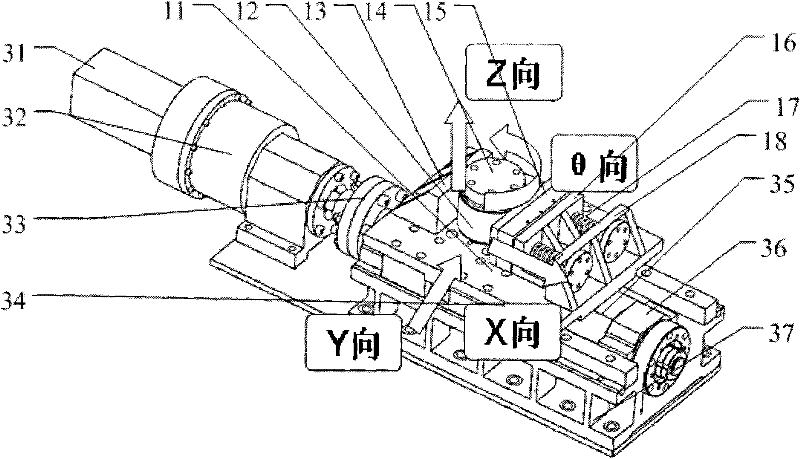
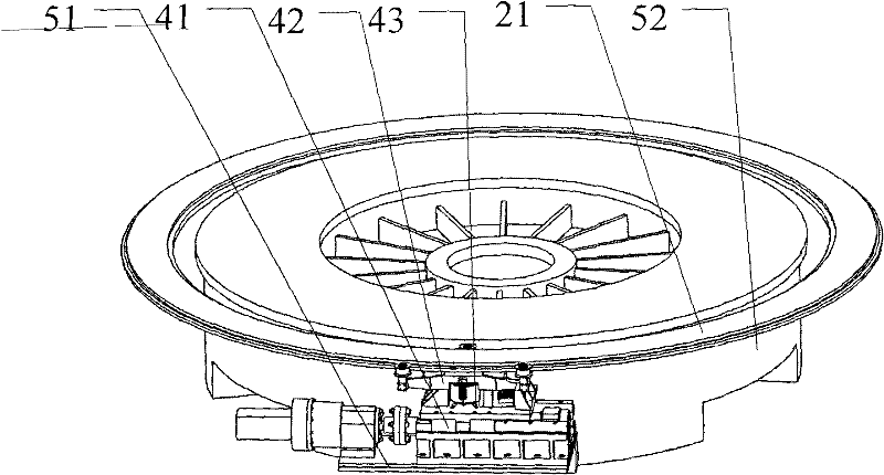
[0020] Such as figure 1 , 3 As shown, the rotary drive device of the present invention includes a linear micro-displacement mechanism 41, a moving plate 11, a push plate 13, a slide plate 15, and rolling elements. Wherein the moving plate 11 , the pushing plate 13 , the sliding plate 15 and the rolling bodies jointly constitute an angular displacement conversion mechanism 43 . The linear micro-displacement mechanism 41 includes a servo motor 31 , a harmonic reducer 32 , a shaft coupling 33 , a rolling guide rail 34 , a ball screw 35 , a bearing seat 36 and a fixed seat 37 . The rolling body adopts a shaft sleeve 12, and a roller or other rolling bodies that can roll can also be used. The moving plate 11 is connected with the linear micro-displacement mechanism 41 and can move linearly along the X direction driven by the linear micro-displacement mechanism 41 . The push plate 13 and the moving plate 11 are integrally structured. The push plate 13 can also be fixedly connect...


PUM


Abstract

The invention relates to a rotary driving device, which comprises a linear micro-displacement mechanism and an angular displacement conversion mechanism; the angular displacement conversion mechanism includes a moving plate, a push plate, a slide plate and a rolling body; the moving plate is connected to the linear micro-displacement mechanism , can move linearly along the X direction under the drive of the linear micro-displacement mechanism; the push plate is fixed on the moving plate; the sliding plate is installed on the moving plate, movably connected with the moving plate, and can move along the Y direction relative to the moving plate; The rolling body is clamped by the push plate and the slide plate, suspended on the moving plate, and the rolling body is movably connected with the rotating body. Since the technology of the linear micro-displacement mechanism is very mature, the precision can reach 0.1 μm or even higher, so the present invention adopts the method of converting the linear micro-displacement into the rotational angular displacement to drive the rotating body to rotate, and the angular positioning accuracy is high.

Description

technical field [0001] The invention relates to a rotary drive device. Background technique [0002] Rotating bodies such as turntables are usually driven by a shaft system to rotate. Generally, a servo motor, a reducer and a gear transmission (or worm drive) are used to jointly drive the shaft system to rotate and position, and some servo motors, reducers and friction wheels are used to drive the shaft system. rotationally positioned. The former not only has a complex structure and a large volume, but also has gaps in multi-stage deceleration and transmission, and low servo rigidity. Although the latter has a simple structure, it is also relatively large in size and has disadvantages such as easy wear and slipping. There are also torque motors that directly drive the shaft system to rotate and position. Obviously, the direct drive of the torque motor has the advantages of simple structure, small size, no gap and high servo rigidity, but only relying on the direct drive of ...

Claims


Application Information

Patent Timeline
Patent Type & Authority Patents(China)
IPC IPC(8): F16H13/08
Inventor 田学光田兴志刘轩刘伟
Owner CHANGCHUN INST OF OPTICS FINE MECHANICS & PHYSICS CHINESE ACAD OF SCI
Why Eureka
Try Eureka