Normally closed micro-mechanical inertia electrical switch

A mechanical inertia and micro-mechanical technology, applied in the direction of electric switches, circuits, electrical components, etc., can solve the problems of circuit false contact, mass electrode without boundary protection, device damage, etc., to prevent false contact, improve contact effect, The effect of preventing damage

Inactive Publication Date: 2010-04-28
SHANGHAI JIAO TONG UNIV
View PDF0 Cites 12 Cited by
  • Summary
  • Abstract
  • Description
  • Claims
  • Application Information

AI Technical Summary

Problems solved by technology

However, in this technology, when the mass electrode collides with another fixed electrode, due to the high stiffness of both, the contact effect is poor, making false contact in the circuit; and the high-speed rebound mass electrode does not have any boundary protection. may cause damage to the device

Method used


Image

  • Normally closed micro-mechanical inertia electrical switch
  • Normally closed micro-mechanical inertia electrical switch
  • Normally closed micro-mechanical inertia electrical switch

Examples


Embodiment 1

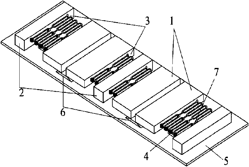
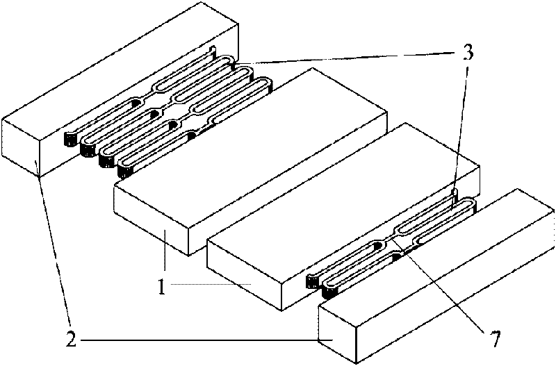
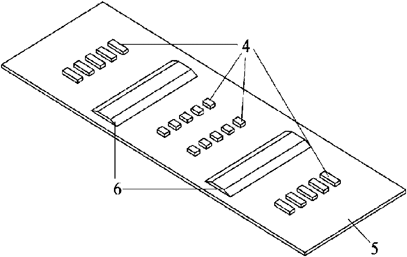
[0027] Such as figure 1 As shown, this embodiment includes: two pairs of mass electrodes 1, three spring support seats 2, four pairs of multi-turn conjoined serpentine springs 3, two support layers 4, an insulating substrate 5, and two fixed contact electrodes 6 and twelve springs connecting body 7, wherein: the fixed contact electrode 6 and the support layer 4 are fixed on the insulating substrate 5; the support layer 4 is located on both sides of the fixed contact electrode 6; the mass electrode 1 is located above the fixed contact electrode 6 , in contact with the fixed contact electrode 6; the spring support seat 2 is fixed on the insulating substrate 5, and is located on both sides of the support layer 4; The other end is connected to the electrode 1 of the mass block; the connecting body 7 between the springs is located in the middle of the connecting snake spring 3, and is connected to the connecting snake spring 3 on both sides respectively

[0028] Such as figure 2...

Embodiment 2

[0034] Such as Figure 4 As shown, the difference between this embodiment and Embodiment 1 is that the number of turns of the one-piece serpentine spring 3 is one turn, and the number of corresponding spring-connected bodies 7 is four.

[0035] This embodiment effectively improves the contact effect between the mass electrode 1 and the fixed contact electrode 6, and prevents the false contact phenomenon of the circuit; Under external impact acceleration, there will be no violent collision with the spring support seat 2, which effectively prevents damage to the device.

Embodiment 3

[0037] Such as Figure 5 As shown, the difference between this embodiment and Embodiment 1 is that each mass electrode 1 includes a 4×8 square hole array, the square holes have a length of 40 microns, a width of 30 microns, and a height of 75 microns.

[0038] This embodiment effectively improves the contact effect between the mass electrode 1 and the fixed contact electrode 6, and prevents the false contact phenomenon of the circuit; Under external impact acceleration, there will be no violent collision with the spring support seat 2, which effectively prevents damage to the device.


PUM


Abstract

The invention discloses a normally closed micro-mechanical inertia electrical switch, and belongs to the technical field of micro-electro-mechanical engineering. The normally closed micro-mechanical inertia electrical switch comprises an insulating substrate, a siamesed serpentine spring, a support layer, a fixed contact electrode, a spring support seat, a mass block electrode and a continuum between springs, wherein the fixed contact electrode and the support layer are all positioned on the insulating substrate; the mass block electrode is positioned above the fixed contact electrode, and is contacted with the fixed contact electrode; the spring support seat is fixed on the insulating substrate and positioned on two sides of the support layer; the siamesed serpentine spring is positioned above the support layer; one end of the siamesed serpentine spring is connected with the spring support seat, while the other end is connected with the mass block electrode; and the continuum between the springs is positioned in the middle of the siamesed serpentine spring and is connected with the siamesed serpentine spring on the two side. The normally closed micro-mechanical inertia electrical switch effectively improves the contact effect between the mass block electrode and the fixed contact electrode; and the mass block electrode cannot collide with the spring support seat violently under outside impact acceleration, so the damage to devices is effectively prevented.

Description

technical field [0001] The invention relates to a device in the technical field of microelectromechanical engineering, in particular to a normally closed micromechanical inertial electrical switch. Background technique [0002] Inertial switches designed and manufactured based on MEMS technology have attracted much attention because of their advantages of small size, low cost and mass production. In the past, the micro-inertial switch, no matter it was driven vertically or horizontally, because its processing method was developed on the basis of traditional integrated circuit manufacturing technology, in many cases the switch was prepared with silicon as the substrate for electroplating. There is unavoidable internal stress, so that the height of the entire device cannot be too thick. In order to obtain a large enough mass to sense the external acceleration, the overall area of ​​the device is finally larger. [0003] At present, the design of miniature inertial electrical...

Claims


Application Information

Patent Timeline
Patent Type & Authority Applications(China)
IPC IPC(8): H01H35/14
Inventor 杨卓青周镇威丁桂甫
Owner SHANGHAI JIAO TONG UNIV
Why Eureka
Try Eureka