Eureka AIR delivers breakthrough ideas for toughest innovation challenges, trusted by R&D personnel around the world.

Bridge expansion joint structure

A technology for expansion joints and bridges, applied in the direction of bridges, bridge parts, bridge construction, etc., can solve the problems of complex construction process, damage to expansion joints, complex materials, etc., to simplify the construction process, save investment costs, and reduce maintenance costs. Effect

Inactive Publication Date: 2010-05-05
潘志洪
View PDF1 Cites 7 Cited by
  • Summary
  • Abstract
  • Description
  • Claims
  • Application Information

AI Technical Summary

Problems solved by technology

The padding material of the expansion joint is on the upper part of the concrete plane of the beam body and the asphalt concrete of the bridge deck, so that a longitudinal gap is formed between the front and rear sides of the expansion joint structure and the road surface of the bridge body, which is easy to cause due to four seasons climate change, rain and snow Weather, freezing, etc. bring about great changes. During normal driving and braking, the extrusion of the expansion joint will cause displacement, which will cause the contrast between the asphalt on the bridge deck and the expansion joint of the beam body due to the inconsistency of the materials used, resulting in rattling during driving. Jumping phenomenon, frequent impact and vibration of the expansion joints of the beam body, and rainwater directly seeping into the expansion joints will easily cause premature damage to the expansion joints
Moreover, the construction process is complicated, and the material used in the padding process of the expansion joint is also too complicated. The polymer particles used in the expansion joint are perpendicular to the beam body and are easy to fall

Method used


Image

  • Bridge expansion joint structure
  • Bridge expansion joint structure
  • Bridge expansion joint structure

Examples


Embodiment Construction

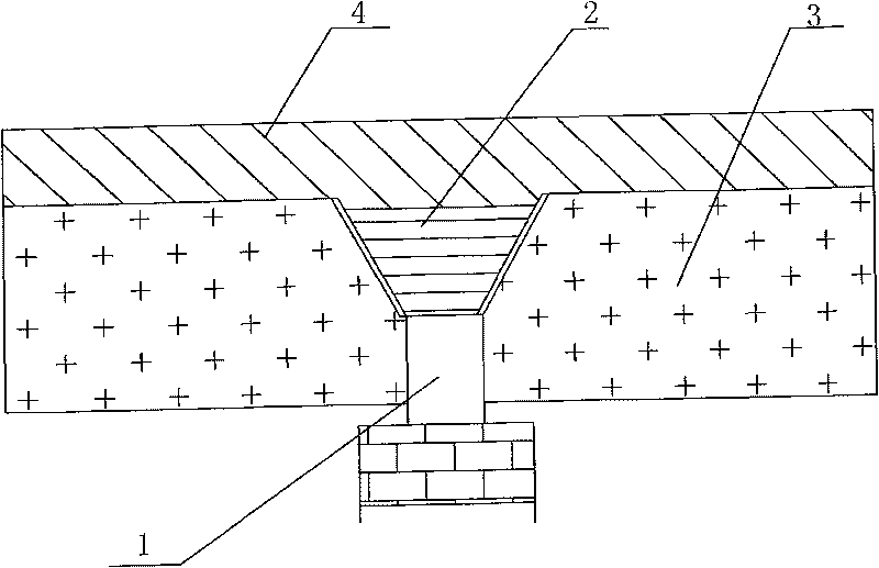
[0016] see figure 1 , figure 1 It is a schematic diagram of the overall structure of the bridge expansion joint structure of the present invention. Depend on figure 1 It can be seen that the bridge expansion joint structure of the present invention includes two adjacent beam bodies 3, the upper parts of the interface ends of the adjacent two beam bodies 3 are arranged as mutually symmetrical inclined planes, and the lower parts are all arranged as vertical planes, so that the adjacent two beam bodies The bridge expansion joint 1 formed between 3 is divided into upper and lower parts: the cross-section of the upper part is an inverted trapezoid with a wide top and a narrow bottom, and the cross-section of the lower part is a rectangle with the same width up and down. A rubber belt 2 is embedded in the inverted ladder-shaped place with a wide top and a narrow bottom. The cross section of the rubber belt 2 is in the shape of a triangular belt, and finally the asphalt concrete 4...


PUM


Abstract

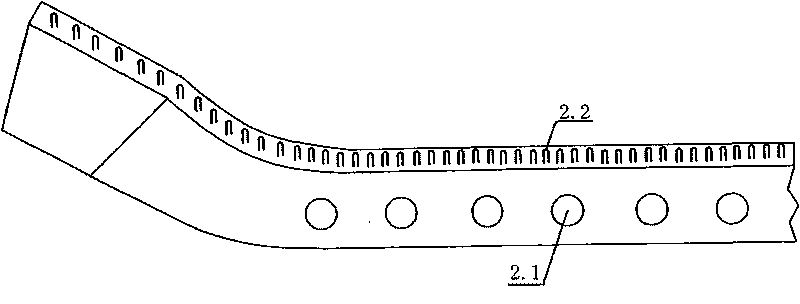
The invention relates to a bridge expansion joint structure comprising two adjacent bridge bodies (3). The upper parts of the connection ends of the two adjacent bridge bodies (3) are provided with mutually symmetric inclined planes and the lower parts are provided with vertical planes, so that a bridge expansion joint (1) formed between the two adjacent bridge bodies (3) is divided into an upper part and a lower part, wherein the cross section of the upper part is an inverse trapezoid, with wide top and narrow bottom, and the cross section of the lower part is a rectangle with identical upper and lower width; and a rubber belt (2) is embedded on the inverse trapezoid of the bridge expansion joint (1) and the section of the rubber belt (2) is in the shape of a triangular belt. Asphalt concrete (4) is directly paved on the whole bridge deck, thus the rubber belt (2) of the bridge expansion joint is closely connected with the asphalt concrete (4) on the bridge deck into a whole. The side wall of the rubber belt (2) is provided with a plurality of pores (2.1) and the surface of the rubber belt (2) is provided with a plurality of small convex columns (2.2). The structure can slow down premature damage of the bridge expansion joint, prolong the service life, ensure the vehicles to pass safely, smoothly and swiftly, simultaneously lower the maintenance cost, save the raw materials and accelerate the construction progress.

Description

(1) Technical field [0001] The invention relates to a bridge expansion joint structure. It belongs to the technical field of road and bridge engineering. (2) Background technology [0002] With the rapid development of urban construction, the development of various transportation facilities is advancing by leaps and bounds. Expressways, urban viaducts, and various bridges have been built one after another. Due to the continuous increase of traffic volume, vehicle speed, vehicle load and some minor problems left in the bridge construction, the damage of bridge expansion joint joints is very common. The damage of the bridge expansion joint joints will cause the vehicle to bump continuously when driving, the noise is disturbing, the phenomenon of jumping is aggravated, and the safety and service life of the bridge are endangered, and the maintenance cost of the bridge is increased. Therefore, its durability, driving stability, and passenger comfort have attracted great atten...

Claims


Application Information

Patent Timeline
IPC IPC(8): E01D19/06
Inventor 潘志洪
Owner 潘志洪
Why Eureka
Eureka Blog
Learn More