Safe floor drain of floating cover

A safe and floating cover technology, applied to waterway systems, drainage structures, water supply devices, etc., can solve problems such as ground water overflow, floor drain sewer blockage, and poor water intake, so as to enhance the ability to resist turbidity and deodorize The effect of long-lasting effect and smooth flow of accumulated water

Inactive Publication Date: 2010-05-05
戴永锋
View PDF3 Cites 6 Cited by
  • Summary
  • Abstract
  • Description
  • Claims
  • Application Information

AI Technical Summary

Problems solved by technology

The floor drain cover of this structure has the following defects: 1. The water hole is opened too small, the orifice is easy to block, the drainage speed of accumulated water is slow, and the ground water is easy to overflow; 2. The water hole is opened too large, and solid impurities Objects are easy to fall into the floor drain, and it is easy to cause the floor drain or even the sewer to be blocked; the large water hole will also easily make the water in the water-sealed deodorant floor drain dry and lose the deodorization function, and the rigidity of the floor drain cover becomes smaller, unsightly, and 3. The orifice shape, size and quantity of the water hole of the same floor drain cover are usually fixed, even if the size of the water hole is designed to be adjustable, as the application number is 200620165639.6 With the floor drain device, the floor drain cover will always become the bottleneck for the rapid discharge of ground water
[0004] Remove the floor drain cover or do not install the floor drain, the drainage is fast and smooth, and its bottleneck effect is eliminated, but it brings new problems. Accidental loss, and slightly larger debris is easy to fall into and easily cause sewer blockage; for the above-mentioned floating cover type floor drain, slightly larger debris falls in the gap of the above-mentioned floating cover type floor drain, and it is very easy to put the cover bowl and the floating ball together It is stuck, making it unable to float normally, making its anti-odor function unreliable, and even unable to drain normally, and the fragile and exposed floating ball is also easily deformed and damaged by collisions with cleaning tools or other objects and trampled by people's feet. Adverse effects of using
Especially, if above-mentioned floating cover type floor drain also arranges and uses the floor drain cover of existing form, can bring new problem again to the use of this floor drain, as: local area water falls vertically from the floor drain cover aperture, will directly The impact on the upper part of the floating ball weakens the floating ability of the floating ball and the bowl, and also weakens the resistance of the floating ball to debris jamming, that is, it has an adverse effect on the floating of the bowl and the floating ball; and when the floating ball floats At this time, the upper top surface of the floating ball is easy to lean against the water hole at the lower end of the floor drain cover, which makes the water inlet channel smaller and narrower, resulting in poor water intake, thereby making the drainage speed slower and the bottleneck of the floor drain cover Defects will be more prominent

Method used


Image

  • Safe floor drain of floating cover
  • Safe floor drain of floating cover
  • Safe floor drain of floating cover

Examples


Embodiment 1

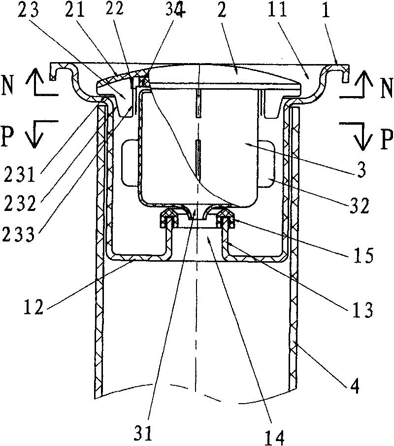
[0031] The floor drain of embodiment 1 of the present invention (structure sees Figure 1-Figure 4 ), including a floor drain seat 1 and a floor drain cover 2 located at its upper end, the lower periphery of the floor drain cover 2 is provided with at least three evenly distributed ribs 23, and the ribs 23 are movably supported on the bottom surface of the floor drain seat , make the rib 23 of the floor drain cover 2 contact the surrounding space of the bottom surface of the seat groove 11 to form a preset water inlet gap, so that the ground water can flow through the water inlet gap and be poured into the floor drain. The floor drain cover 2 of the present invention is preferably a non-orifice floor drain cover.

[0032]The upper end of the floor drain seat 1 is provided with a seat groove 11, so that the above-mentioned floor drain cover 2 is placed in the seat groove 11, and a predetermined water entry gap is provided between the floor drain cover 2 and the side wall of the...

Embodiment 2

[0050] The floor drain of embodiment 2 of the present invention (structure sees Figure 5-8 ), including a floor drain seat and a floor drain cover located at its upper end, the upper end of the above-mentioned floor drain seat is provided with a seat groove, so that the above-mentioned floor drain cover is placed in the seat groove, and the floor drain cover and the side wall of the seat groove of the floor drain seat There is a predetermined water entry gap between them, and the lower side of the seat groove is close to the upper end of the floor drain pipe installed in the floor or the ground, so that the upper end of the floor drain seat is at the same level as the floor (or floor tile surface) or a slightly lower position above, so that the ground water flows from the top of the floor drain cover and into the water inlet gap between the side of the seat tank and the floor drain cover, and passes through the preset water inlet gap formed by the surrounding space where the f...

Embodiment 3

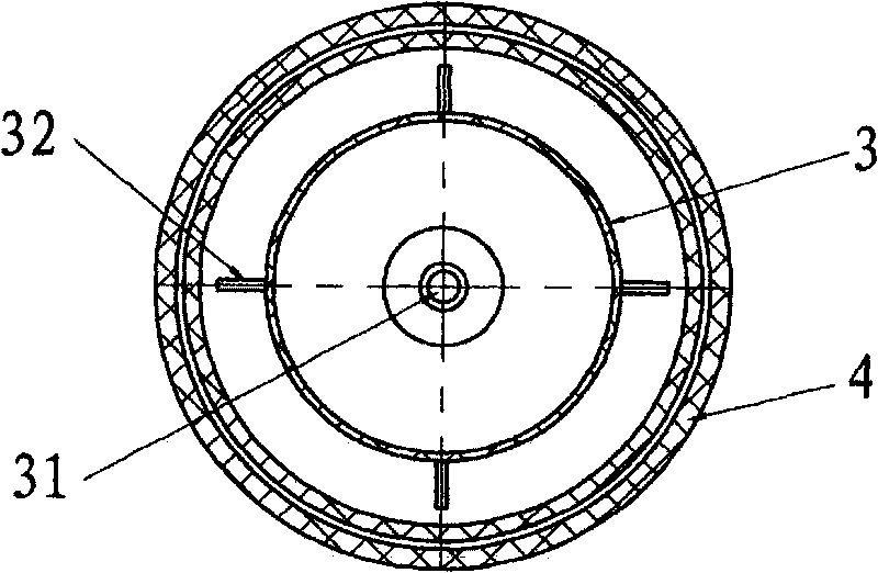
[0062] The floor drain of embodiment 3 of the present invention (structure sees Figure 9-13 ), including a floor drain seat 1 and a floor drain cover 2 located at its upper end, the floor drain seat 1 is indirectly provided with a drain hole 14, and a floating cup 3 is provided on the port of the drain hole 14, and the bottom surface of the floating cup 3 can be sealed in On the port of the drain hole 14, the floor drain cover 2 is a hat-shaped cover plate 21 with a cap opening 24, and the upper end of the above-mentioned floating cup 3 is sleeved in the cap opening 24 of the floor drain cover 2, and the floor drain cover 2 and the A predetermined water inlet gap is arranged between the floor drain seats 1, so that ground water flows through the gap and poured into the floor drain, so that the floating cup 3 floats, and the accumulated water in the floor drain is discharged into the sewer.

[0063] More specifically, the floor drain of Embodiment 3 of the present invention (s...


PUM


Abstract

The invention discloses a safe floor drain of a floating cover, comprising a floor drain seat and a floor drain cover positioned on the upper end part of the floor drain seat. The safe floor drain is structurally characterized in that the upper end part of the floor drain seat is provided with a seat slot; the floor drain cover is positioned in the seat slot; a preset water inlet gap is formed between the floor drain cover and the side wall of the seat slot of the floor drain seat; a preset water inlet gap is arranged between the floor drain cover and the bottom surface of the seat slot; the lower end part of the floor drain seat is provided with a seat bottom which is provided with a drainage hole; the drainage hole is provided with a floating cup encapsulated on an end port; a water inlet gap is kept on the inner side surface of the floating cup corresponding to the floor drain seat; and a water inlet gap is kept between the floating cup and the bottom surface of the seat bottom of the floor drain seat. The floor drain cover floats by the action of buoyancy through the deodorant structure of the floating cup; the water inlet gaps are increased to enable floor water to smoothly flow in from the circumference of the end port of the floor drain seat; and the flowing speed of the floor water can approach or reach a non-setting state or the state without the floor drain cover.

Description

Technical field: [0001] The invention relates to a floor drain, which belongs to a floor drain especially suitable for indoor use. Background technique: [0002] In the existing floor drain with a cover, the accumulated water on the ground will flow from the end face of the floor drain cover and then fall into the floor drain from the water hole on the floor drain cover or be discharged into the sewer (although the accumulated water can be drained from the floor drain cover and the floor drain seat). leaked through the gap, but only accounted for a negligible small part, the gap is not used as a drainage channel, and it is very easy to be filled and closed by fine dirt and sludge in the stagnant water). The floor drain cover of this structure has the following defects: 1. The water hole is opened too small, the orifice is easy to block, the drainage speed of accumulated water is slow, and the ground water is easy to overflow; 2. The water hole is opened too large, and solid ...

Claims


Application Information

Patent Timeline
Patent Type & Authority Applications(China)
IPC IPC(8): E03F5/04
Inventor 戴永锋
Owner 戴永锋
Why Eureka
Try Eureka