
Thermal buffer tube and thermoacoustic system

A technology of thermal buffer tube and thermoacoustic system, applied in the field of thermoacoustics

Inactive Publication Date: 2012-11-07
LIHAN THERMOACOUSTIC TECH SHENZHEN
View PDF5 Cites 0 Cited by
  • Summary
  • Abstract
  • Description
  • Claims
  • Application Information

AI Technical Summary

Problems solved by technology

[0004] In the process of realizing the present invention, the inventors found that there are at least the following problems in the prior art: Although it is possible to add a small thin-walled pipe to the thermal buffer pipe in the existing thermoacoustic system To a certain extent, the generation of natural convection is reduced, but small thin-walled pipes are easy to destroy the uniformity of fluid flow in the pipes, and the small thin-walled pipes themselves will also cause the loss of fluid heat conduction, reducing the performance of the thermoacoustic system

Method used


Image

  • Thermal buffer tube and thermoacoustic system
  • Thermal buffer tube and thermoacoustic system
  • Thermal buffer tube and thermoacoustic system

Examples


Embodiment Construction

[0025] In order to make the purpose, technical solutions and advantages of the embodiments of the present invention clearer, the technical solutions in the embodiments of the present invention will be clearly and completely described below in conjunction with the drawings in the embodiments of the present invention. Obviously, the described embodiments It is a part of embodiments of the present invention, but not all embodiments. Based on the embodiments of the present invention, all other embodiments obtained by persons of ordinary skill in the art without creative efforts fall within the protection scope of the present invention.

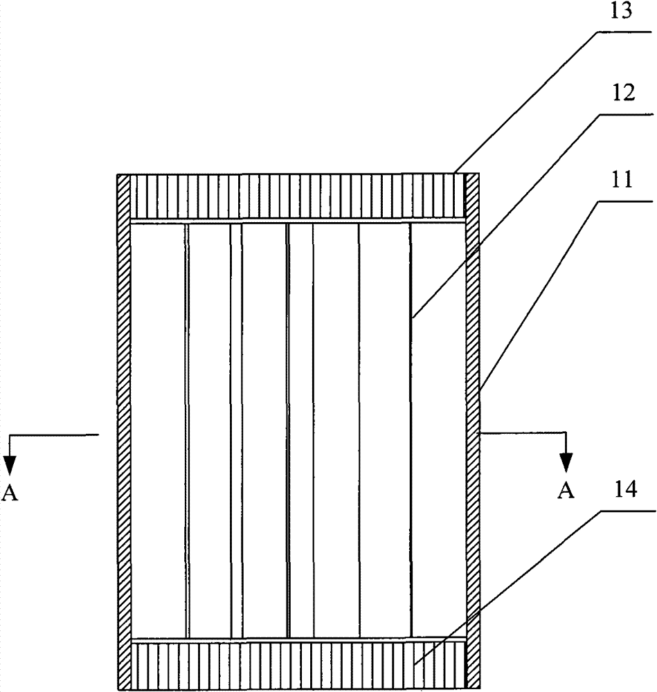
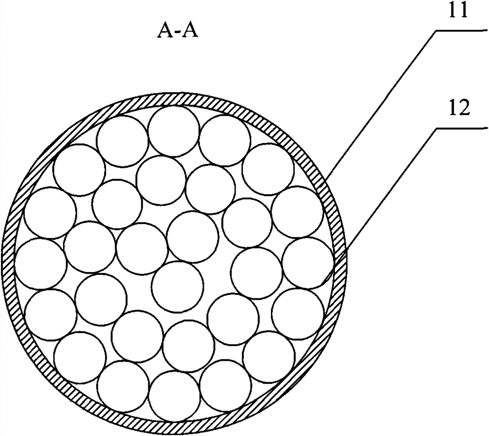
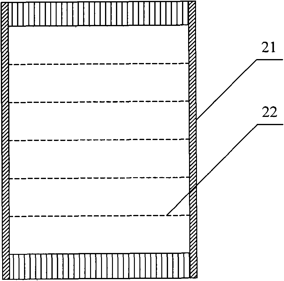
[0026] In view of the natural convection phenomenon of the fluid in the thermal buffer tube of the thermoacoustic system, and the loss of cold and heat caused by the natural convection phenomenon, the inventor proposes a thermal buffer tube in which a porous baffle is set , to reduce and avoid the natural convection in the thermal buffer tube, red...


PUM


Abstract

The invention provides a thermal buffer tube and a thermoacoustic system. The thermal buffer tube comprises a pipe body. Porous baffles are arranged between the hot end and the cold end of the pipe body in the axial direction and are used for inhibiting natural convection in the pipe body. The thermoacoustic system comprises the thermal buffer tube. By arranging the porous baffles in the thermal buffer tube, the technical scheme of the invention can effectively inhibit natural convection in the thermal buffer tube, reduce the losses of heat and cold quantities in the thermal buffer tube and improve the thermal efficiency of the thermoacoustic system.

Description

technical field [0001] Embodiments of the present invention relate to the field of thermoacoustic technology, in particular to a thermal buffer tube and a thermoacoustic system. Background technique [0002] A thermoacoustic system is a system that uses the thermoacoustic effect to convert heat energy into mechanical energy in the form of sound waves or convert mechanical energy in the form of sound waves into heat energy through the alternating flow of gas, including thermoacoustic engines, such as traveling wave thermoacoustic engines and Stirling engines, etc., as well as thermoacoustic refrigerators, such as traveling wave thermoacoustic refrigerators, pulse tube refrigerators, and Stirling refrigerators. In the thermoacoustic system, the thermal buffer tube is a circular pipe, and the two ends of the circular pipe are called the cold end and the hot end respectively. When the system is working, the fluid in the thermal buffer tube generally reciprocates in the equilibri...

Claims


Application Information

Patent Timeline
Patent Type & Authority Patents(China)
IPC IPC(8): F02G1/053F25B23/00F25B9/14
CPCF25B2309/1408F25B2309/1406F25B2309/1414F25B9/145
Inventor 胡剑英罗二仓戴巍李海冰
Owner LIHAN THERMOACOUSTIC TECH SHENZHEN
Learn More