Metal material double-moving-die pressure forming method and device based on suspension melting matching
A metal material and driving device technology, which is applied in the field of double-moving die pressure forming methods and devices for metal materials based on suspension fusion, can solve the problems of poor service performance, small parts, and low single-piece/small batch production efficiency, etc. Improve service performance, inhibit natural convection and buoyancy, and reduce shrinkage
- Summary
- Abstract
- Description
- Claims
- Application Information
AI Technical Summary
Problems solved by technology
Method used
Image
Examples
Embodiment 1
[0081] Include the following steps:
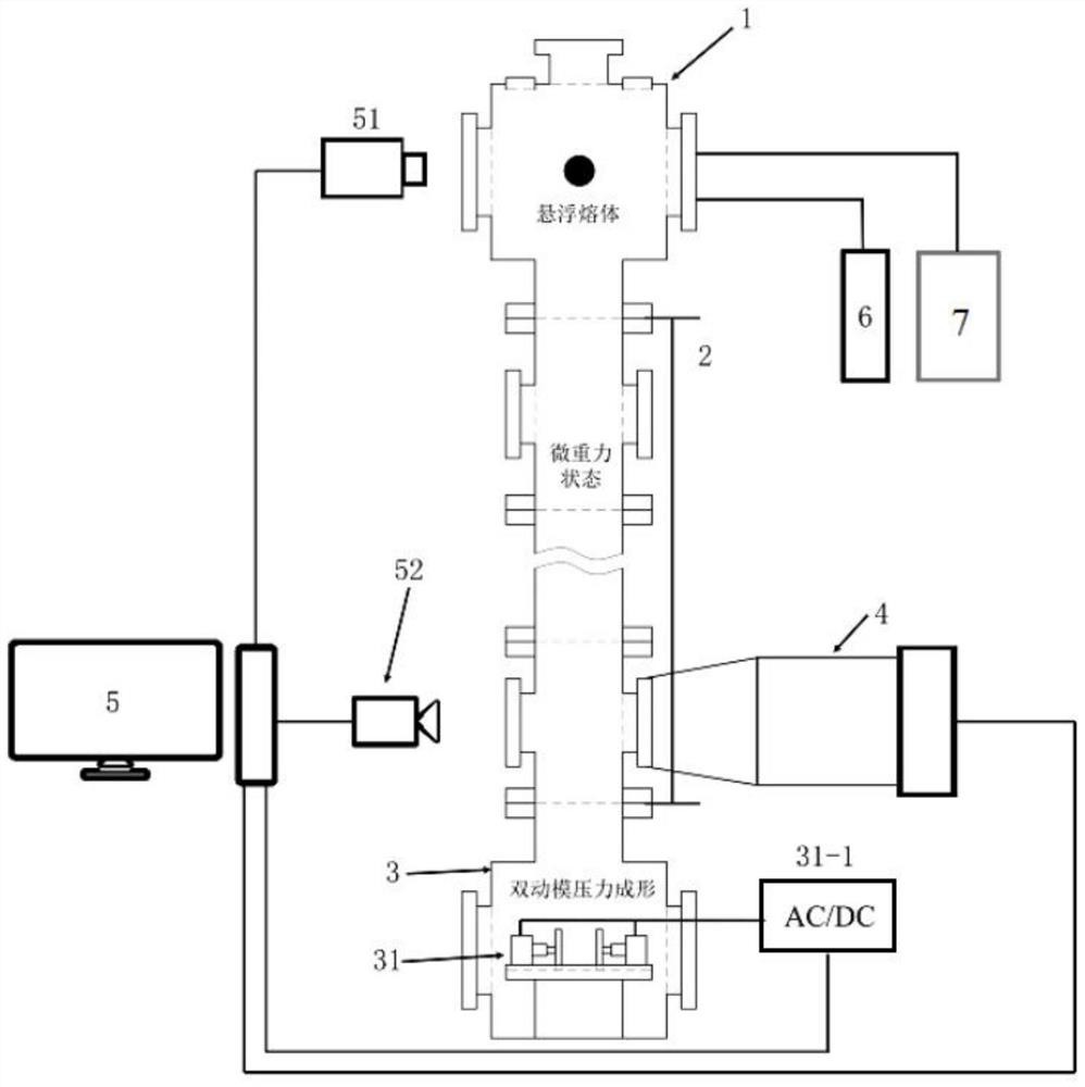
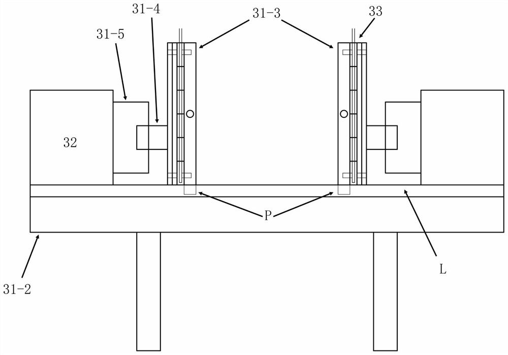
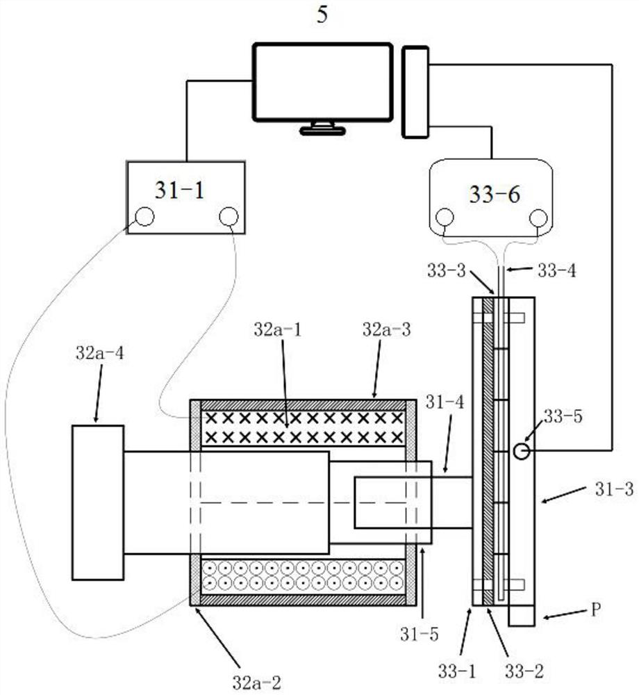
[0082] Step 1. Install an electrostatic levitation device in the containerless state chamber 1, adjust the microgravity chamber 2 to 1500 mm, select an AC electromagnet device optimized for vacuum environment as the drive device 32 and 2 such as Figure 4 The metal movable mold 31-3 of copper cylindrical shape shown is ready for installation in the pressure forming chamber 3. Select the pressure delay control mode in the integrated control system 5 to delay the power on after the suspension stop signal is detected, with a delay of 590ms, and set the mold pressure holding time in the integrated control system 5 to 3000ms. Adjust the voltage of the power supply 31-1 (AC power supply) to 110V. Zr with a diameter of 2mm 60 Ni 25 al 15 The ball is loaded into the vacuum chamber;
[0083] Step 2. Turn on the vacuum pump system 4 to pump the vacuum chamber to 1×10 -5 Pa, and Zr 60 Ni 25 al 15 The ball is sent to the appropriate hanging p...
Embodiment 2
[0090] Include the following steps:
[0091] Step 1. Install an electromagnetic levitation device in the containerless state chamber 1, adjust the microgravity chamber 2 to 1000 mm, select an AC electromagnet device optimized for a vacuum environment as the driving device 32 and a molybdenum square metal movable mold 31-3, one side of which is For such Figure 4 Shown square metal moving mold 31-3, the other side is for having special-shaped groove, overflow groove and exhaust duct such as Figure 5 The cavity movable mold 31-3a shown is ready for installation in the pressure forming chamber 3. Select the pressure delay control mode in the integrated control system 5 to delay the power on after the suspension stop signal is detected, with a delay of 490ms, and set the mold pressure holding time in the integrated control system 5 to 5000ms. Adjust the voltage of the power supply 31-1 (AC power supply) to 110V. Put AA2024 aluminum alloy balls with a diameter of 500mm into the...
Embodiment 3
[0099] Include the following steps:
[0100] Step 1. Install a pneumatic levitation device in the containerless state chamber 1, select Ar gas as the levitation power gas, splice the microgravity chamber 2 to 3000mm, select a vacuum stepping motor as the driving device 32 and such as Figure 4 Shown stainless steel square metal moving mold 31-3, and in pressure forming chamber 3 installation ready. In the integrated control system 5, the delay control mode is selected to be energized after the photodetector 52 detects that the molten metal has fallen to a suitable height. Fix the photodetector 52 to the observation window of the microgravity chamber 2 at the bottom, delay for 45 ms, and set the mold holding time in the integrated control system 5 to 500 ms. Adjust the voltage of the power supply 31-1 (AC power supply) to 220V, and set the motor propulsion speed to 1m / s in the integrated control system 5 . Ti with a diameter of 300mm 85 Ni 10 al 5 Alloy balls are loaded in...
PUM
| Property | Measurement | Unit |
|---|---|---|
| diameter | aaaaa | aaaaa |
| height | aaaaa | aaaaa |
Abstract
Description
Claims
Application Information
 - R&D
- Intellectual Property
- Life Sciences
- Materials
- Tech Scout
- Unparalleled Data Quality
- Higher Quality Content
- 60% Fewer Hallucinations
Browse by: Latest US Patents, China's latest patents, Technical Efficacy Thesaurus, Application Domain, Technology Topic, Popular Technical Reports.
© 2025 PatSnap. All rights reserved.Legal|Privacy policy|Modern Slavery Act Transparency Statement|Sitemap|About US| Contact US: help@patsnap.com


