
Active vibration isolation platform

An active vibration isolation and platform technology, applied in the direction of non-rotational vibration suppression, can solve the problems of limited output bandwidth, complex equipment, high cost, etc., and achieve the effect of convenient design

Inactive Publication Date: 2010-05-05
SHANGHAI INST OF OPTICS & FINE MECHANICS CHINESE ACAD OF SCI
View PDF0 Cites 34 Cited by
  • Summary
  • Abstract
  • Description
  • Claims
  • Application Information

AI Technical Summary

Problems solved by technology

However, passive vibration isolation has its inherent disadvantages: first, the damping ratio requirements for resonance amplification and high-frequency attenuation are contradictory, and the damping ratio must be considered comprehensively during design, and a compromise must be made; secondly, in order to increase the effective bandwidth of the vibration isolator, it is necessary to reduce the The natural frequency of the vibration isolator, but considering the structural realization and equipment installation accuracy, the support stiffness of the vibration isolator should not be too low, and the passive vibration isolator cannot attenuate low-frequency vibration
Hydraulic actuators can produce large displacement and output force, but the output bandwidth is limited and the equipment is complicated. The effective bandwidth of the same pneumatic actuator and shape memory alloy actuator is also limited, not exceeding 10Hz. Piezoelectric actuator And the output displacement of the magnetostrictive actuator is very limited, it is difficult to be competent for low frequency vibration control
[0005] The STACIS active vibration isolation platform developed by TMC uses AVI, which is composed of a piezoelectric actuator and PVI in series. Since the actuator has to bear all the load, the selected piezoelectric actuator has a diameter of 25.4mm and a height of 32mm, which is expensive.

Method used


Image

  • Active vibration isolation platform
  • Active vibration isolation platform
  • Active vibration isolation platform

Examples


Embodiment Construction

[0022] The present invention will be further described below in conjunction with the embodiments and accompanying drawings, but the protection scope of the present invention should not be limited thereby.

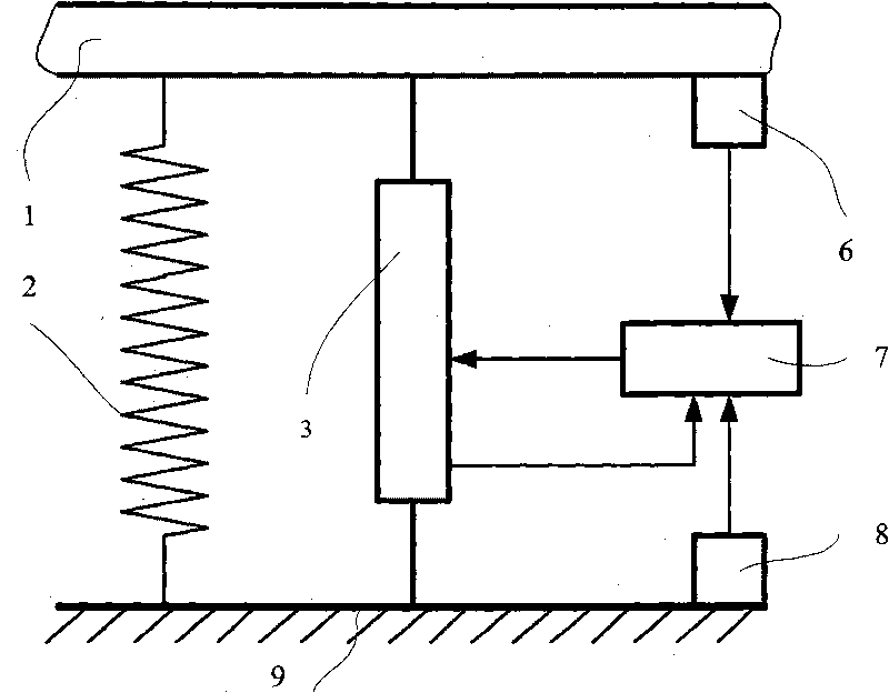
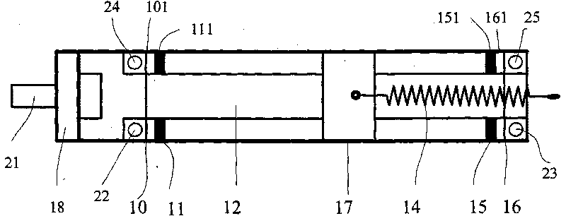
[0023] see first figure 1 , figure 1 It is a schematic diagram of a single-degree-of-freedom model of the active vibration isolation platform of the present invention. The structure of the active vibration-isolation platform of the present invention includes a platform 1 supported by multiple air springs 2 and multiple single-degree-of-freedom vibration isolation modules. The single-degree-of-freedom vibration isolation The module is composed of a motor actuator 3, a first sensor 6, a controller 7, and a second sensor 8. The motor actuator 3 is composed of a motor with a mover or rotor 13 and a stator 12 and a drive spring 14, so The air spring 2 is connected between the foundation 9 and the platform 1, the stator 12 of the motor is fixedly connected with the foundation 9,...


PUM


Abstract

The invention relates to an active vibration isolation platform which comprises a platform, a sensor, a controller and an electrical actuator. The active vibration isolation platform has the working principle that the sensor measures the vibrations of the groundsill and platform; the controller controls the output of the electrical actuator according to the measurement signal of the sensor and a certain control algorithm; the rotor of the motor is connected with the platform through an actuating spring, and outputs displacement or angular displacement according to the control command of the controller; the displacement output is converted to force output by the actuating spring, or the angular displacement output is converted to a moment output, thereby reducing the platform vibrations; high-frequency noise can not be transferred by the electrical actuator of the invention; and the electrical actuator of the invention has larger output stroke and output force.

Description

technical field [0001] The invention relates to vibration control, in particular to an active vibration isolation platform. Background technique [0002] There are usually three methods of vibration control: weakening the strength of the vibration source, vibration isolation and vibration absorption. Vibration isolation is to increase the vibration attenuation components between the vibration source and the vibration damper. Generally, a passive vibration isolator (PVI-Passive Vibration Isolation) composed of a spring and a damper is used, such as an air spring vibration isolator. It has been widely used because of its simple structure and reliable performance. However, passive vibration isolation has its inherent disadvantages: first, the damping ratio requirements for resonance amplification and high-frequency attenuation are contradictory, and the damping ratio must be considered comprehensively during design, and a compromise must be made; secondly, in order to increase...

Claims


Application Information

Patent Timeline
IPC IPC(8): F16F15/02
Inventor 张涛刘芳徐嘉黄宏彪赵芳芳孙平平朱健强
Owner SHANGHAI INST OF OPTICS & FINE MECHANICS CHINESE ACAD OF SCI
Learn More