Multifunctional triaxial core clamping device

A core clamping, multi-functional technology, applied in the field of oilfield exploration and development, can solve the problems of ineffective utilization, single function, high cost, etc., and achieve the effects of saving test costs, reliable technical conditions, and simple structure

Inactive Publication Date: 2010-05-05
青岛石大石仪科技有限责任公司
View PDF0 Cites 27 Cited by
  • Summary
  • Abstract
  • Description
  • Claims
  • Application Information

AI Technical Summary

Problems solved by technology

[0002] Using geometric similarity to establish an indoor model to simulate the actual stress state of the rock in the formation is the main means of indoor exploration and development research. The commonly used core test devices in the research are uniaxial, biaxial or pseudo triaxial. The simulation The situation cannot represent the real situation of the formation, and there will be some errors between the obtained results and the actual results. Although relevant theoretical derivations can be used to correct them, the theoretical results still need to be verified by experiments.
There are also a few true triaxial core test devices at home and abroad, which use large presses and hydraulic components to provide power. The scale is too large, it is expensive to start and cannot be used effectively, and it has a single function and can only be used for testing. Research on the true triaxial failure mechanism of rocks, but cannot conduct seepage tests, simulated fracturing, etc.

Method used


Image

  • Multifunctional triaxial core clamping device
  • Multifunctional triaxial core clamping device
  • Multifunctional triaxial core clamping device

Examples


Embodiment Construction

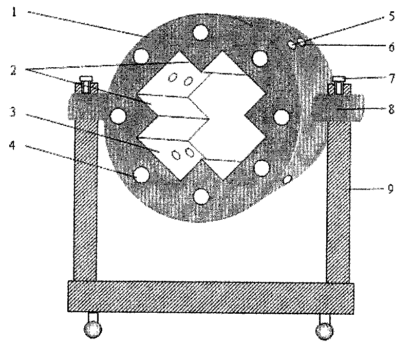
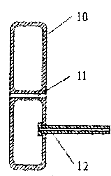
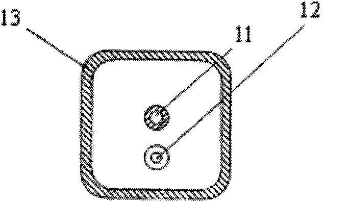
[0028] refer to figure 1 The main body 1 is a metal cylinder with a through hole in the middle along the axial direction. The cross section of the through hole is in the shape of a "ten" as a whole, and four opposite grooves 2 are formed in space for placing the side hydraulic bladder 10. , the depth of the groove 2 is consistent with the thickness of the hydraulic bladder 10 . There are two through holes on the bottom surface 3 of the groove 2, one is located at the center of the bottom surface, which is the test hole 5, and the other is located at the center of the lower half, which is the hydraulic joint hole 6 of the hydraulic bladder. The top surface and bottom surface of the main body are processed with evenly distributed threaded holes 4, and there are two rotating shafts 8 relatively distributed on both sides of the outer cylindrical surface of the main body 1. The axes of the two rotating shafts 8 are on the same line. The axes intersect vertically and form an includ...


PUM


Abstract

The invention discloses a multifunctional triaxial core clamping device, mainly comprising a main body, an upper end cover, a lower end cover, hydraulic bags, rubber magnet, a liquid flow plug, a strain indication rod, an optical fiber tube and a bracket. The main body is a metal cylinder; the center of the main body is provided with a through hole; four opposite grooves are arranged on the periphery of the through hole and internally provided with the hydraulic bags; the central position in the middle part on the bottom surface of each groove is provided with a test hole which is internally provided with the strain indicating rod of a rubber tube arranged through the middle part; the central position of the lower part of the test hole is provided with a hydraulic bag connector hole whichis internally provided with a hydraulic bag connector; the upper end cover and the lower end cover are arranged at the upper end and the lower end of the main body and mutually connected by bolts; square grooves are symmetrically arranged in the centers of the upper end cover and the lower end cover and internally provided with end face hydraulic bags; the bottom surfaces of the grooves are vertically provided with two upward through holes, wherein one hole positioned in the center is the test hole which is internally provided with the strain indicating rod; the other hole is the hydraulic bag connector hole which is internally provided with the hydraulic connector; and a core is arranged in the main body which is arranged on the bracket through a rotating shaft.

Description

1. Technical field [0001] The invention relates to test equipment used for rock mechanical performance and seepage performance analysis in the field of oil field exploration and development, and is a multipurpose rock core clamping device that can truly simulate the stress state of underground rock. 2. Background technology [0002] Using geometric similarity to establish an indoor model to simulate the actual stress state of the rock in the formation is the main means of indoor exploration and development research. The commonly used core test devices in the research are uniaxial, biaxial or pseudo triaxial. The simulation The situation cannot represent the real situation of the formation, and there will be some errors between the obtained results and the actual results. Although relevant theoretical derivations can be used to correct them, the theoretical results still need to be verified by experiments. There are also a few true triaxial core test devices at home and abroa...

Claims


Application Information

Patent Timeline
Patent Type & Authority Applications(China)
IPC IPC(8): G01N3/04G01N3/12G01N15/08
Inventor 邵东亮李晓东任荣亭朱金堂
Owner 青岛石大石仪科技有限责任公司
Why Eureka
Try Eureka